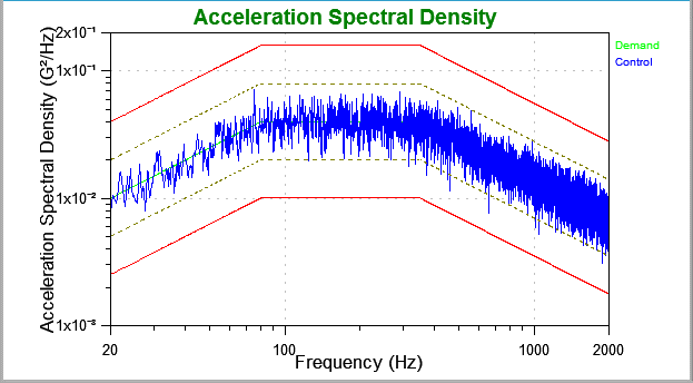
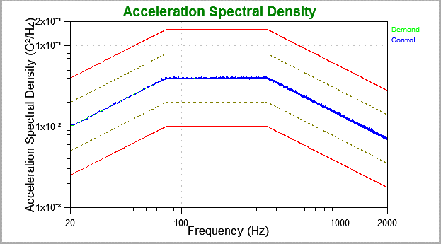
During the ramp-up of a random vibration test, engineers want to see a smooth line centered within the tolerance bands on the power spectral density (PSD) plot. A smooth ramp-up indicates that the test is within requirements, while raggedness on the PSD can be concerning. Equipment such as satellites and airplanes are expensive, and the engineers cannot accept an out-of-tolerance condition.
However, does a smooth ramp-up show the engineer what is actually occurring on the shaker table? The answer is, in short, no. Some raggedness at the beginning of a test is typical for PSD estimation. A smooth ramp-up line on a random PSD indicates that the data are inaccurate, which should be a concern. During ramp-up, the drive signal might overshoot low-level tolerances before settling into the control, and resonance can shift when a test steps up a level.
The following video shows a ramp-up of a basic random test to level, and averaging to the target DOF.
Ramp-up in Random Testing
A random vibration test produces a PSD that helps engineers identify resonances within the frequency range of interest. To estimate the PSD, the control software applies the fast Fourier transform (FFT) to frames of the data and then averages the power values of the FFTs. The engineer sets the degrees of freedom (DOF) value, which determines the amount of averaging the software uses to estimate the PSD. The test will appear out of tolerance until the software has enough data to estimate the PSD with sufficient confidence.
Ramp-up describes the period between the test starting and when it reaches level. After the ramp-up starts, the data will begin to average, and an estimation error will cause the line to bounce in and out of tolerance. After the average reaches the desired degrees of freedom, the PSD should be a smooth line unless there is a control error.
Graph Display Options
Vibration control software typically displays ramp-up data in one of three ways. However, there are PSD estimation methods that are misleading and can lead to more significant issues later in the testing process. Some engineers don’t distinguish estimation error from control error and treat any raggedness as a negative. They have adopted methods to circumvent estimation errors, putting their test item at risk of over- or under-testing.
1. Display Real-Time Data
Control software programs can display real-time data during ramp-up. At first, this option may not seem ideal because a random signal requires a certain amount of averaging to produce a smooth response line. When the test starts, the software spends a short time collecting and averaging data. Therefore, a random graph will inherently be choppy, but only initially. As the test progresses, the line will average and smooth out. The more time spent averaging, the smoother the line.
2. Mask Data with a Delay
One popular—but inaccurate—PSD estimation method uses low-level data to obtain a smooth line and then applies a multiplier to show product behavior at a higher level. The software generates a smooth line at a high level almost instantly but at the cost of an inaccurate test. Products behave differently during a change in level than at full level, and using a multiplier masks what is occurring on the shaker table.
3. Mask Data Using Prediction
This third method of displaying ramp-up data also uses averaging. The software predicts the demand level and precedes it with the calculated average, factoring in the new data as time passes. The graph only displays the response at the beginning. As the software accumulates sufficient data, the PSD line updates to show real-time random data.
This method does not display the actual results during the ramp-up period but the expected results (low-level results multiplied by step amplification factor). Although it shows data customers like to see, it is not factual.
An Analogy
 Consider the following analogy: per a test specification, a car must accelerate from 0 to 60mph in 1 second. This requirement is not entirely feasible, as controllers cannot display all the test data in this short of a time. No controller can ramp up that quickly while meeting the demand level. The test has to display real-time data or mask the data so the graph fits the specification.
Some controllers would display a reading of 0 to 60mph on a speedometer over 1 second; that is to say, after 0.001 seconds, the speedometer would read 60mph and never change. If a speedometer performed like this, it would indicate something was working improperly. This masked data displays an expectation, not real data.
Historically, controllers have not displayed real data during a ramp-up. Therefore, engineers are unaccustomed to seeing it on graphs. Ramp-up data that sometimes exceeds tolerance and abort lines can concern test professionals.
Many controller manufacturers attempt to meet expectations by masking real-time ramp-up data through prediction. They run a low-level signal (such as 10% of the desired level), then multiply the output by a factor of 10. If the output is multiplied by 10, then the input is also expected to multiply by a factor of 10. The software uses all the readings in the initial ramp-up stage to show the expected input.
The Problem with Averaging
No one wants to see a product fail during ramp-up. But what if it is the perfect time for failure to occur? What if the resonances that the product experiences during ramp-up do not appear in the random test? Results can change and resonances can shift during test level changes, and the product may see these resonances during operation. If control errors are masked by the control software, it may leave test professionals scratching their heads when the product “meets” testing requirements yet continues to fail in the field. A more realistic approach is to present the true data as it occurs during ramp-up.
iDOF: An Accurate PSD Estimation Method
Vibration Research understands how important it is for engineers to have a smooth day at the office. We are also committed to using accurate testing methods. As the innovator in vibration control, our team of engineers developed a statistically accurate way to remove estimation errors while displaying control errors. Our advanced test module, Instant Degrees of Freedom (iDOF), provides smooth lines and an in-tolerance PSD in a brief testing period.

Standard random test with no control error.

iDOF test with no control error.
If a fast and accurate smooth line is important for your vibration testing, download our whitepaper to learn more about iDOF.
