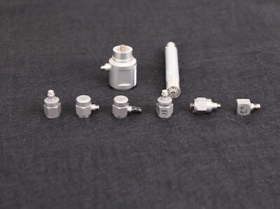
 The material in an accelerometer produces an electrical charge proportional to the excitation force, and force is directly proportional to acceleration. An accelerometer should only measure acceleration in its defined direction of measurement. Cross-axis acceleration occurs when an accelerometer experiences a vibration input from a direction perpendicular to its measurement axis.
An accelerometer’s cross-axis sensitivity indicates the percentage of its output that is susceptible to accelerations on a perpendicular axis. More specifically, it is a percentage ratio of the maximum cross-axis sensitivity to the sensitivity of the measurement direction. The manufacturer provides this value and may alternatively label it as transverse sensitivity.
Typically, cross-axis acceleration is due to the misalignment of sensitivity in the measurement direction. Accelerometer manufacturers take action to keep transverse sensitivity low and thereby prevent cross-axis acceleration. A value of 1-5% is typical for most transducers.
Cross-axis Matrix
Each measurement axis has two sensitivities. For example, a triaxial accelerometer has six cross-axis sensitivities, and its cross-axis matrix looks as follows.
S=[Sxx, Sxy, Sxz, Syx, Syy, Syz, Szx, Szy, Szz]
The first subscript is the measurement axis, and the second is the cross-axis direction.
Significance in Aerospace Testing
Cross-axis acceleration can affect the measurement of the desired axis and lead to error. However, it does not usually contribute to measurement uncertainty. Specialized applications, particularly those at low frequencies, are more likely to define an allowable percentage ratio.
Engineers in the aerospace industry often turn to test standards to set control parameters or tolerances. Yet, the guidance aerospace test standards provide on cross-axis acceleration is limited.
Cross-axis Acceleration in Aerospace Test Standards
Common standards for aerospace testing include those provided by NATO and national defense departments as well as independent organizations for commercial aircraft.
- STANAG 4370
- AECTP 400
- MIL-STD-810 (United States)
- Def Stan 00-35 (United Kingdom)
- RTCA DO160 (United States)
- EUROCAE/ED-14 (Europe)
- IEC60068 and 60721
- BS EN 60068-2-64:2008
There are many standards associated with specific industries. However, many refer to those above or use the same control parameters/tolerances.
For single-axis testing, MIL-STD-810H states, “The motion induced by the vibration generator should be such that the fixing points of the test item move substantially parallel to the axis of excitation.” Less than fifty percent of accelerations out of axis should be below 500Hz and less than 100% above 500Hz. If exceeded, the engineer should identify and address the source.
DEF STAN 00-35 offers the same guidance as 810H with a caveat: the out of axis overall RMS should not exceed 50% of the specified in-axis vibration. BS EN 60068-2-64:2008 requires the same as DEF STAN 00-35.
RTCA DO160 for commercial aircraft has no explicit requirement. It states, “Motion should be parallel and fixture rigid and symmetrical.”
Engineers should look for cross-axis accelerations at the fixing points. The standards in the above list don’t offer any significant guidance regarding cross-axis acceleration, so the general recommendation is to report any acceleration above the defined levels.
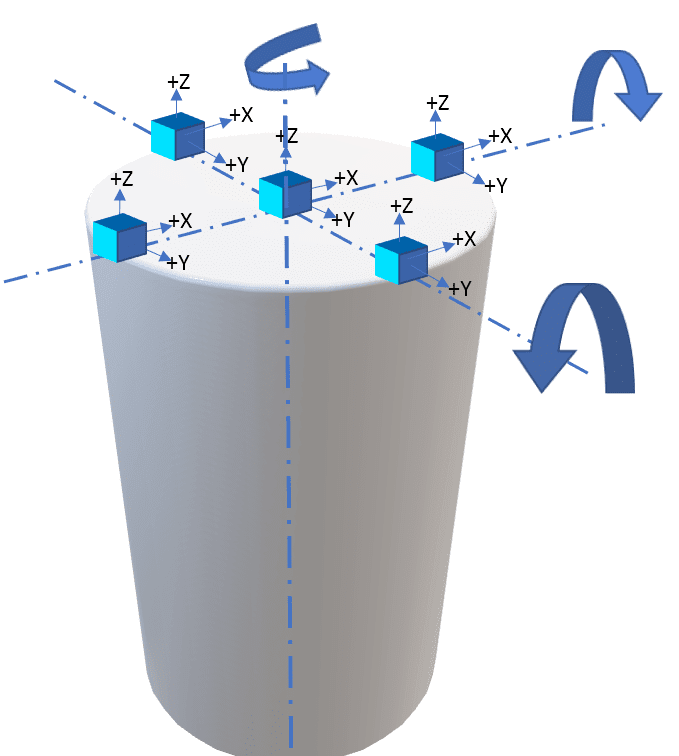
Rigid Rotational Motions of Shaker Armature
When evaluating fixture response, engineers should consider the different motions of the shaker armature. The following is a simplified image of an armature with several measurement positions at its top surface. The arrows indicate potential rotation, and the x, y, and z labels indicate the possible response directions depending on the armature’s movement.
An armature has the potential to undergo different motions. Its responses at the measurement points may differ depending on the location of the rotation. The engineer will also see varying responses to rotational moments on the bottom bearing. The following shows the potential rotations around an armature’s top and bottom surface.
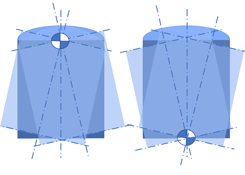
The addition of a head expander also affects the fixture’s response.
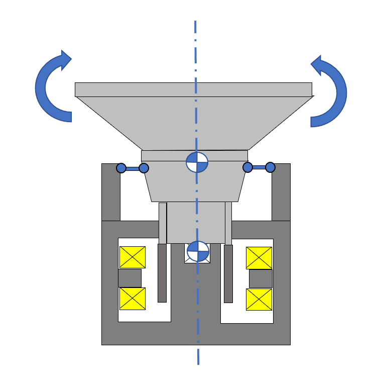
Armature/Fixture Mode Shapes Effect on Cross-axes
In addition to the suspension modes of the armature, an engineer may notice diaphragming in the mode shapes of the head expander and armature. The diaphragming of a fixture’s armature and resonance can lead to large cross-axis motions at specific frequencies. Engineers should look out for phase shifts due to resonances in the measurement channels.
How to Avoid Cross-axis Accelerations
Preventative Maintenance
Set up a regular maintenance test and compare the cross-axis measurements of your bare armature/slip table. When you have your system installed, make sure to take baseline measurements for reference.
In the VibrationVIEW software:
- Save a graph layout with the baseline traces for comparison
- Cut/paste measurements into graph layouts
Measurement Channels
When it comes to aerospace testing, the more measurement channels, the better. We recommend at least 16 channels and five triaxial accelerometers to measure the response of the armature and the input.
Consider running a cross-axis test during testing because the armature/expander response can change depending on what is occurring with the test item.
In the VibrationVIEW software:
- Generate automated test reports
- Add the triaxial measurement of fixture attachments to test reports
- Add math traces to show the limits of different standards
Precursor Tests
Run a precursor test to search for fixture resonances before installing the test item.
In the VibrationVIEW software:
- Perform a precursor test at low-level or full level
- Review transfer function, coherence, and phase relationships (cross-spectrum)
Control/Measurement Accelerometers
Position the control/measurement accelerometers close to the test item/fixture interface.
In the VibrationVIEW software:
- Use multi-channel average/maximum control
- Measure the cross-axis to determine to limit/abort the test
Spectrum Notching/Limiting
After identifying the cause of cross-axis motion, create a limit or notch profile.
In the VibrationVIEW software:
- Set up notch profiles
- Notch on the total force applied to the structure (force limiting)
Download Demo Software
Download the free demo of VibrationVIEW today to set up and design tests before running them on a shaker, view and playback data files, and more. Interested in learning more? View the VibrationVIEW control software features.