For those new to vibration testing, the vast knowledge on the subject can be overwhelming. Some basic information to get you started can go a long way, which is why we’ve outlined five things you should know about the basic vibration tests: sine, random, and shock.
Sine Testing
- Purpose of Sine Testing
Sine testing is not comparable to the vibration we experience in the world. Rather, sine testing is a tool for engineering evaluation and equipment maintenance. Test engineers run a sine test for a defined purpose, knowing that its effect on the device under test (DUT) does not reflect the operational environment.
- Phase
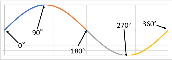
A test engineer can compare two sine waves with the same frequency using phase. Two signals are out of phase when they are not at the same point in the cycle at a specified time.
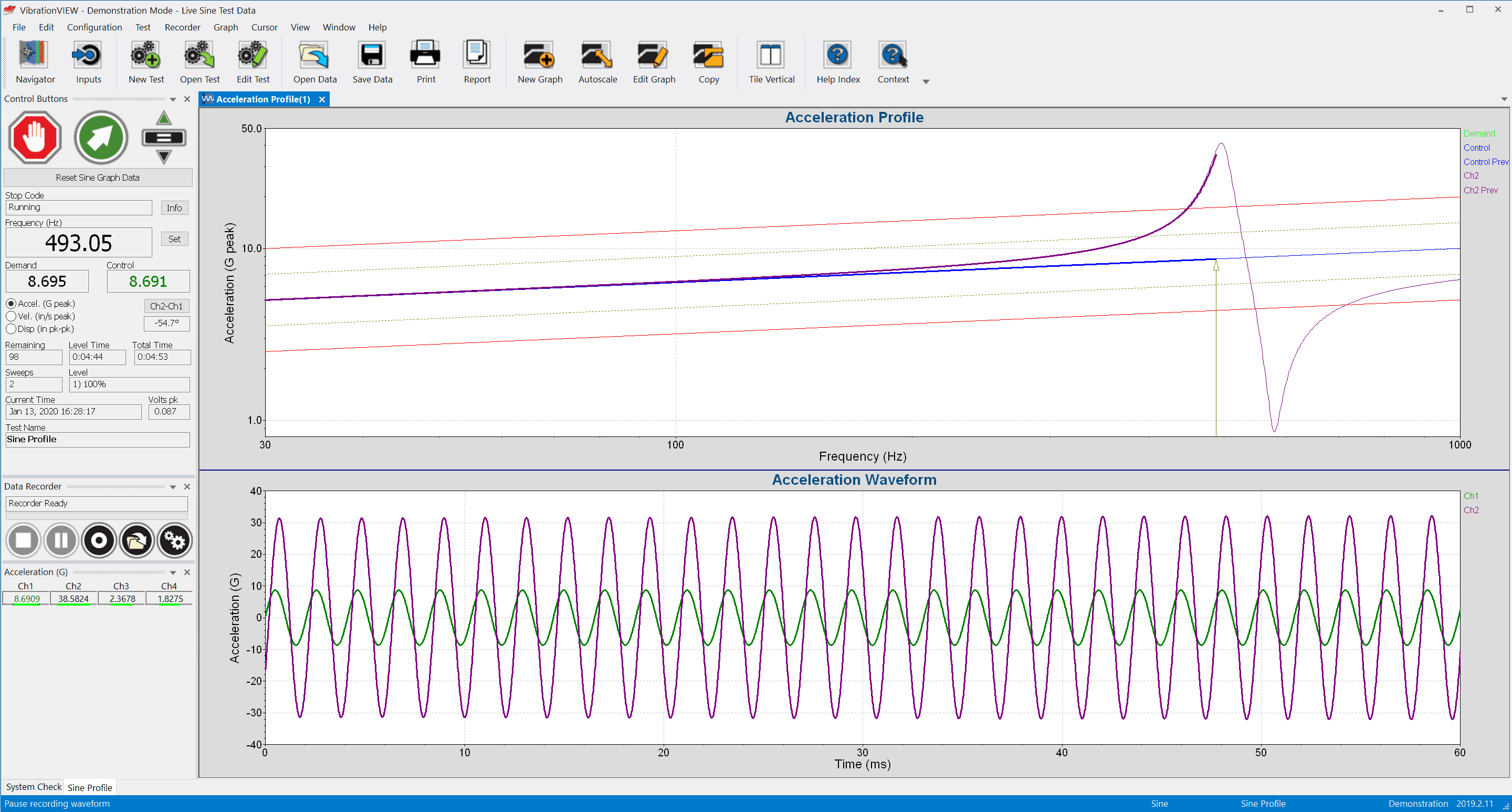
- Vibration Resonance
The sine test is one of the best methods for identifying resonances. Resonance occurs when the frequency of an external force is the same, or nearly the same, as a structure’s natural frequency. This input amplifies the structure’s frequency response, which will result in structural fatigue or damage.
- Sine Sweep Test
To determine a resonance, a test engineer runs a sine sweep test. A sine sweep outputs a single sine tone with a frequency level that varies across a defined range.
TIP: A sine sweep may be a single run from a minimum to maximum frequency, from the maximum to minimum value, or from minimum to maximum and back to the minimum. The definition of a sweep depends on the software.
- Sine Resonance Track & Dwell (SRTD)
A test engineer runs an SRTD test after the sine sweep test determines the resonances. An SRTD test brings a product to failure by exciting the structure’s known resonance(s). The vibration controller runs a single sine tone at the resonant frequencies rather than through the frequency range. The operator runs the test until failure occurs or sufficient time has passed without failure.
Popular Sine Glossary Terms
- Total harmonic distortion (THD) is the summation of the amplitudes of various harmonics when a pure sine tone is entered into a system. It measures how accurately a vibration system reproduces the output signal from a controller and is expressed as a ratio of the harmonic components to the fundamental frequency.
- The frequency spectrum describes the resolution of an electrical signal into its frequency components and provides the amplitude (and sometimes phase) of each component.
- An accelerometer is a sensor, transducer, or pickup that converts acceleration into an electrical signal.
 Learn more in the Sine Vibration Testing course on VRU.
Random Testing
- Power Spectral Density (PSD)
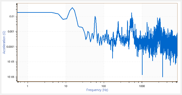
The PSD is the most common tool for analyzing random vibration. It represents the distribution of a signal over a frequency spectrum, and the plot can consist of an infinite number of waveforms.
- G2/Hz
The magnitude of a PSD is the signal’s mean-square value. The average mean-square value is a convenient measurement of signal strength because its average mean value is near zero. It is also necessary for combining signals of different frequencies.
The PSD algorithm divides the mean-square value by the sample rate to normalize it to a single hertz. For an acceleration waveform, the PSD units are G2/Hz.
- Root Mean Square (RMS)
Definition: root mean square (RMS) is a statistical measurement defined as the square root of the signal’s mean-square value.
Engineers take the square root of the mean-square to calculate a linear value of the signal’s magnitude. For an acceleration waveform, the root-mean-square uses the unit GRMS.
After an engineer defines the PSD, the GRMS value does not change. As such, engineers can match a PSD to a test specification with a required GRMS value. They can also use this value to compare two PSD plots with the same parameters and verify that their measurements have the same amount of energy.
- Random Breakpoint Table
A breakpoint table is an arrangement of the random test profile. The engineer defines the frequency and amplitude values and the crossover slope, and the PSD plot displays the values they input into the table.
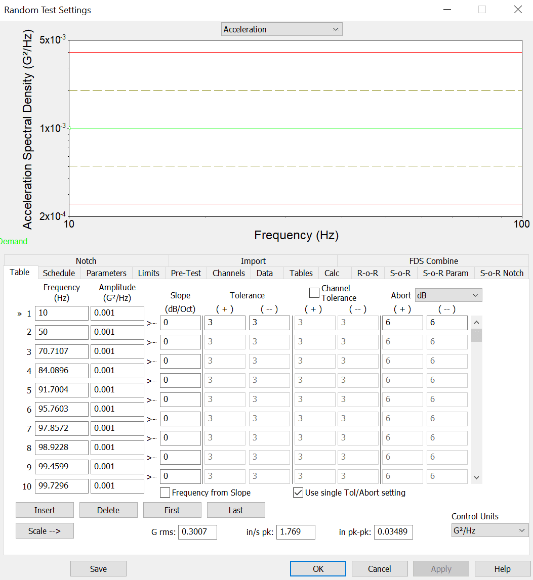
Random breakpoint table in VibrationVIEW.
- Signal Averaging
Definition: averaging is the process of summing and dividing several like measurements to improve accuracy or lessen the effect of any asynchronous components.
One time sample does not provide an accurate PSD magnitude. An engineer can improve the accuracy of the PSD by averaging the PSD computed from successive samples of a signal.
Tip: The degrees-of-freedom (DOF) value determines the number of independent pieces of information that make up the frequency data. A higher DOF will produce smoother lines but will slow down the controller’s display of input signal changes.
Popular Random Glossary Terms
- The cross-spectral density (CSD) compares one signal with another signal in time, such as the drive signal with an input signal.
- Root mean square (RMS) is a statistical measurement defined as the square root of the mean of the squares of a sample. The RMS determines the average intensity (amplitude) in the PSD.
- The fast Fourier transform (FFT) is a computer method of shifting data from the time domain to the frequency domain.
 Learn more in the Random Vibration Testing course on VRU.
Shock Testing
- Shock Pulse
Definition: a shock pulse is an event that transmits kinetic energy into a system in a relatively short interval compared with the system’s greatest natural period.
A vibration shock test inputs a sharp transfer of energy into a mechanical system to test its capability to withstand some source of transient vibration. The shock pulse it uses excites a range of frequencies in a short period and dampens quickly. The pulse is either a classical shock pulse or a transient representation of a recorded event.
- Pre/post-pulse compensation
Shock machines use some mechanical method to halt the table on which the product is mounted, but vibration shakers do not have this capability. Shakers can only generate a fixed velocity and displacement, and continuous values can be damaging. Therefore, pre-/post- compensation pulses are necessary to stop the generated signal.
- Peak Amplitude
Definition: the peak is an extreme value of a varying quantity and measured from the zero or mean value. It is also a maximum spectral value.
The shape of the waveform determines the pulse’s frequency and the degree to which it is excited. The peak amplitude value specifies the maximum value of the shock pulse. The peak amplitude has a defined control unit, typically the acceleration unit G.
Although most classical shock pulses are defined in terms of acceleration, the main purpose of a shock test is to generate a change in velocity and inspect its effect on the product.
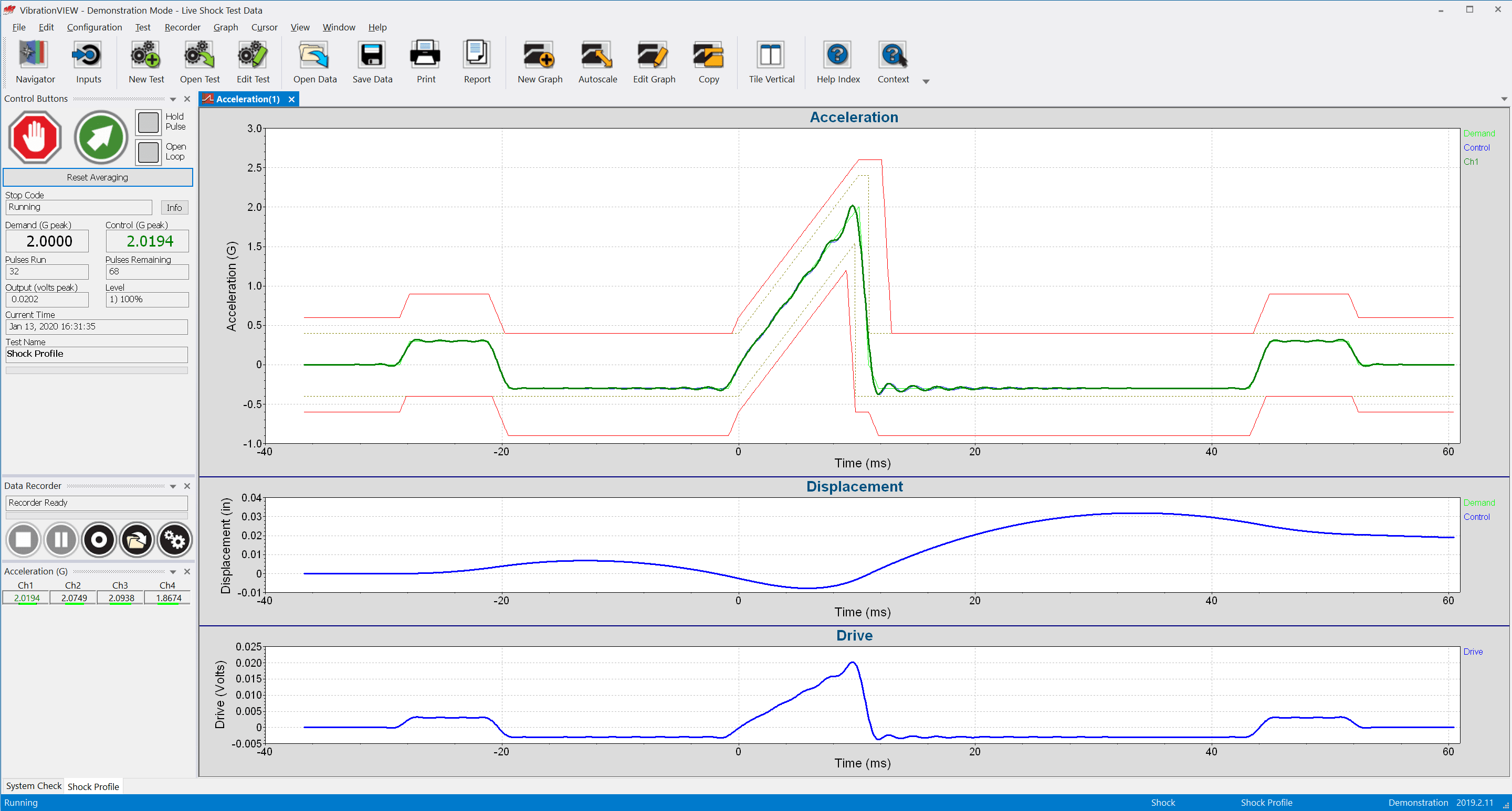
- Test Profile Limits
A shock test standard will define tolerance and abort limits for the test. The tolerance parameters define the peak acceleration value at which the controller switches from startup mode to run mode. The abort parameters define the peak acceleration at which the controller aborts the test.
Tip: VibrationVIEW includes pre-defined limits for common standards such as MIL-STD, DO-160, and EN 60068-2-27.
- Shock Response Spectrum (SRS)
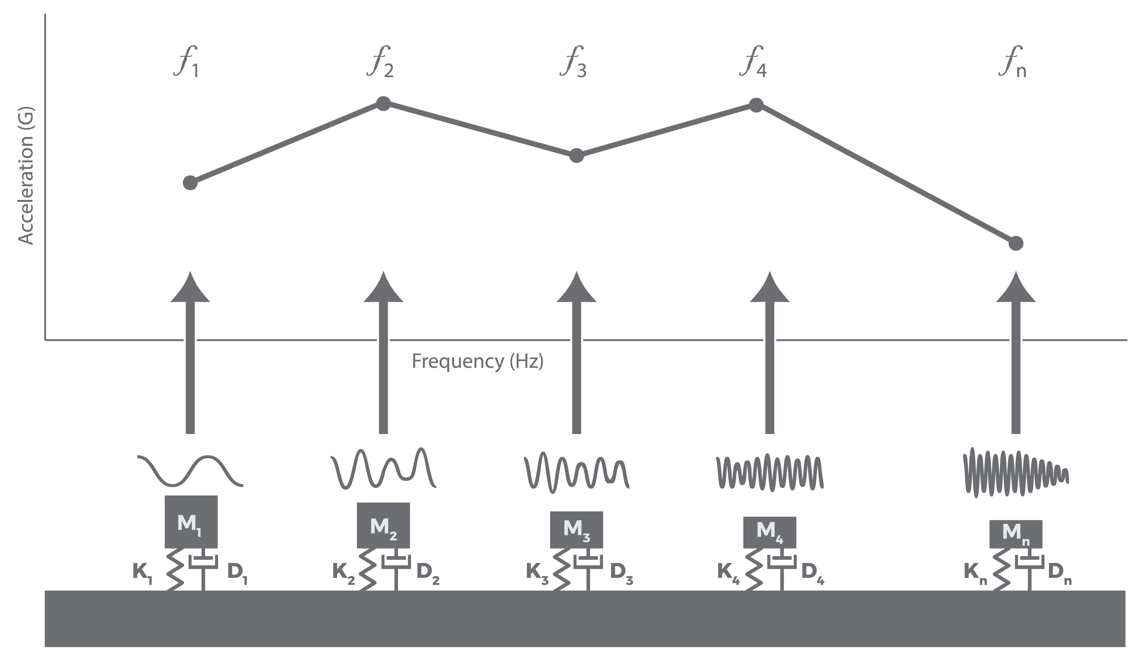
A basic model of the SRS.
Definition: the shock response spectrum (SRS) is a plot of the maximum responses of imagined single-degree-of-freedom systems versus their natural frequencies as they respond to an applied shock.
The SRS is a vibration testing tool for environments with complex shock events. Engineers use an SRS test to evaluate a device’s response to a transient event likely to occur in the operational environment. An SRS test generates more complex shock pulses than a classical shock test. To replicate a specific SRS response, engineers often synthesize one of several standard synthetic waveforms.
Popular Shock Glossary Terms
- The device under test (DUT) or unit under test (UUT) is the product being tested on the shaker system.
- The haversine shock pulse is a practical variation of the obsolete half-sine pulse whose abrupt transitions at beginning and end cannot be achieved in test labs. Practical testing requires some rounding, and the result is called a haversine pulse.
- Velocity is the rate of change of displacement with time, usually along a specified axis. It may refer to angular motion or uniaxial motion.
 Learn more in the Sine Vibration Testing course on VRU.
The Basics of Setting Up A Vibration Test
Looking for more information on the basics of vibration testing? Download our free e-book on setting up and running a vibration test.