Electrical noise can impact vibration controller performance. Noise often appears as an irregularity or distortion in the test signal plot, potentially leading to inaccurate test results or system malfunctions.
In most cases, electrical noise in a vibration control system originates from two primary sources: ground loop noise and electromagnetic interference (EMI). These issues can introduce complications, ranging from minor disturbances to equipment damage. Engineers need to be aware of these potential noise sources to ensure reliable and accurate vibration testing.
EMI
Electromagnetic interference (EMI) is a common challenge in vibration testing environments. Everyday electronic devices—such as power tools, garage door openers, and fluorescent light ballasts—can be sources of EMI. These operating devices emit electromagnetic waves that can propagate through the surrounding area and disrupt sensitive equipment.
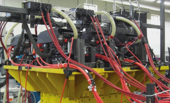
Vibration testing systems are susceptible to EMI from equipment or external sources. Long or poorly shielded cables, some components, and vibration amplifiers may inadvertently function as antennae, capturing EMI and channeling it into the system. This interference can corrupt the test signals, leading to unreliable data or equipment damage. Test engineers should be proactive in mitigating the impact of EMI.
Ground Loop Noise
In electrical and electronic systems, “ground” has two meanings depending on the context.
- In power electricity, ground is a physical connection to the earth (earth ground)
- In electronics, ground is a reference point to 0 volts (0 V)
A ground loop occurs when multiple devices with a ground to the electrical power system are connected through a signal or communications cable that also has a reference ground connection. This setup creates multiple paths to ground through various devices that can form a loop or loops. The loops pick up interference currents, creating electrical noise.
When engineers use the ground as a 0-volt reference, it is the basis for measuring other voltages generated throughout the system. This reference is no longer exactly 0 V when affected by a ground loop, which can cause errors in the measurements used by the system.
Vibration control systems have a complete ground connection through a set of interconnecting cables from 1) the controller output to the amplifier, 2) the amplifier to the shaker, 3) the shaker to the control sensor, and 4) the control sensor to the controller input.
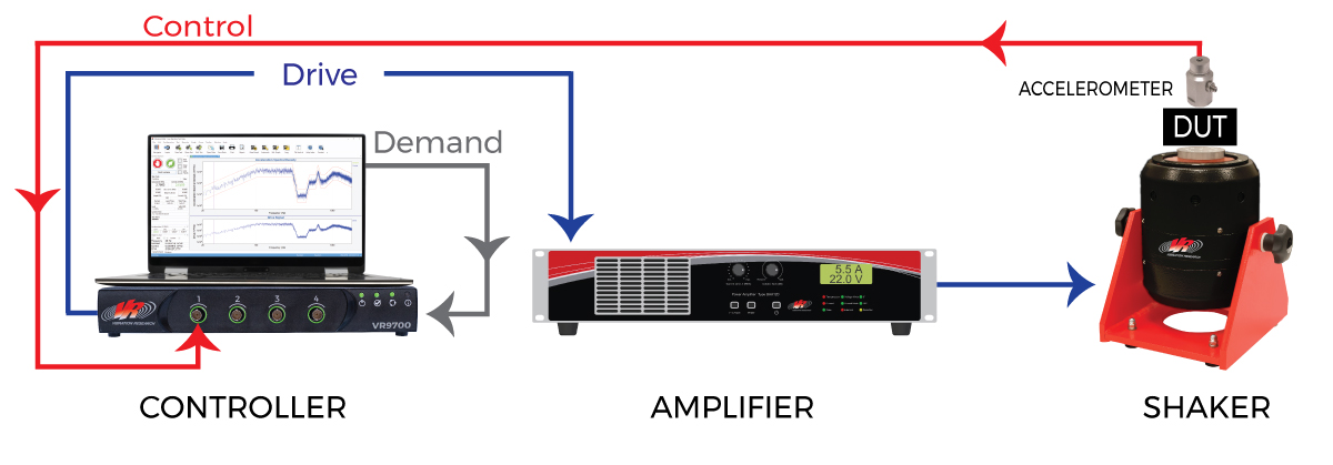
In addition to this complete loop of single-point ground references, the controller, amplifier, and shaker have safety ground references to earth ground. These multiple references to earth ground and the interconnected cabling all have an extremely high potential for creating ground loops.
Breaking the Ground Path
 Vibration systems integrated with equipment like thermal chambers, hydraulic systems, or auxiliary data acquisition systems are more susceptible to ground loops due to multiple chassis grounds.
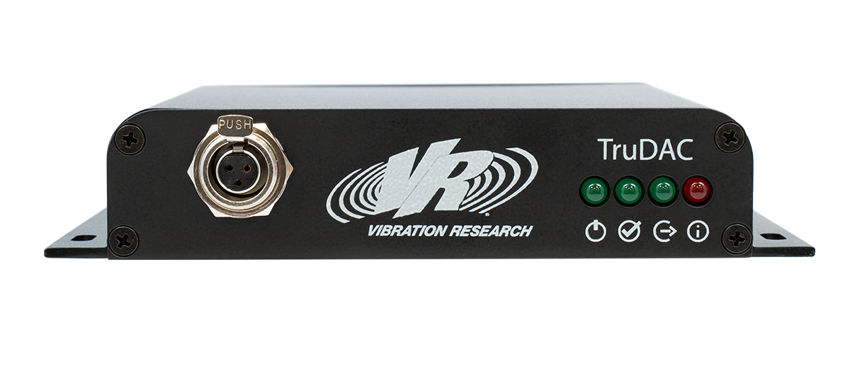
The TruDAC breaks the ground path between the controller and the amplifier, preventing ground loops and electrical noise. Its transformer-coupled digital input separates ground references operating at different potentials, and its analog outputs are fully isolated from ground.
The TruDAC addresses EMI challenges by breaking potential ground loops. Its digital drive interface also reduces the possibility of electrical interference coupling into an analog circuit.
VR9700 Double-insulation
Eliminate Ground Loops Through the Controller
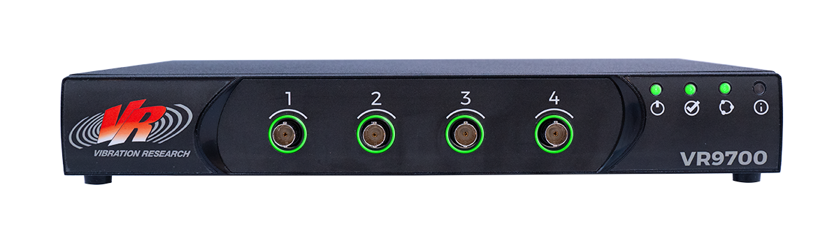
The VR9700’s double-insulated chassis eliminates the potential for ground loops through the controller’s safety ground. In many control systems, ground loops are created between external components (shaker, amplifier) through the drive cable or accelerometer cables to the controller’s chassis/safety ground. This particular ground loop is a common source of external noise in a vibration controller. Double insulation eliminates this path to ground and prevents external components from attempting to source a ground reference through the controller.
In addition to the isolated power, the inputs and outputs are also ground isolated, breaking additional potential paths for ground loops.
Learn More
Our System Noise and Ground Loops VRU course gives more details on noise and ground loops, plus detailed steps for troubleshooting noise problems in your vibration testing system.