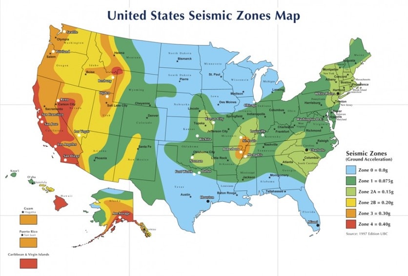
Telecommunications equipment on some North American networks must conform to hardware requirements to avoid damage or malfunction imposed by environmental stressors such as seismic events. Installed equipment is susceptible to temperature, humidity, vibration, and contamination, and malfunctions pose a risk to safety and efficiency. Vibration, in particular, can inflict damage during transport and natural disasters or introduce fatigue over a longer duration.
Article Overview
- Overview of the Telcordia (Bellcore) GR-63-CORE standard (NEBS) and its purpose
- Explanation of why vibration testing matters to ensure long-term reliability
- Description of GR-63’s vibration-related test methods
- Step-by-step test process example
- Coverage of test software and tools, such as VibrationVIEW
Telcordia GR-63-CORE
The Network Equipment Building System (NEBS™) created the Telcordia GR-63-CORE standard (formerly Bellcore) that defines the “minimum spatial and environmental criteria” for equipment in these regions.
GR-63 provides general requirements for telecommunications equipment, including how to plan space accordingly, design considerations, and environmental conditions and test methods. This article addresses the test methods for vibration, which are specific to handling, transportation, office use, and earthquakes.
Other specifications provide more specific design requirements for telecommunications equipment, such as electrical requirements, and GR-63 is one of several documents that define vibration testing methods for this equipment type. Additional standards for seismic testing of telecommunications equipment and others include:
- IEEE/IEC 60980-344
- ICC-ES AC156
- IEEE 693
- IEC 60068-3-3
Engineers may also develop a custom test profile based on historical or recorded data to better simulate the operational environment of the equipment.
Criteria
The document’s vibration environmental criteria define equipment operation, storage, and transportation in the event of a shock, vibration, or earthquake. Exposure may include:
- As equipment goes through handling and shipment, it may experience shock events from being dropped (packaged or unpackaged)
- Random vibration from internal or external factors may compromise functionality over time
- Seismic events may damage frames, chassis, and circuit packs/connectors
Test Methods
GR-63 provides the conditions for drop shock testing. Drop tests use a basic shock pulse to run a sharp transfer of energy into the test item.
GR-63 also provides a required response spectrum for more complex seismic testing, which acts as the test demand for a defined frequency range. Engineers must test their equipment on all three axes, and test severity depends on the equipment’s installation location.
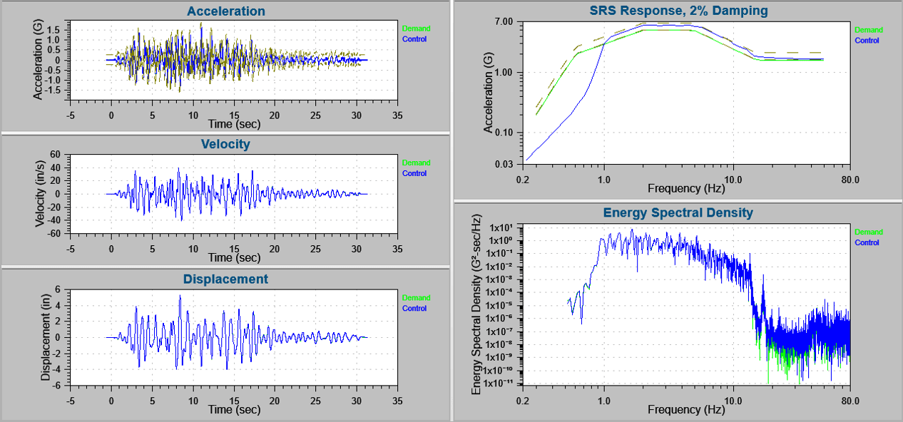
Displacement and acceleration data. For seismic testing, the engineer must verify that the test response spectrum (TRS) exceeds the required response spectrum (RRS) in the designated frequency range.
Following testing, the engineer must survey the permanent structural and mechanical damage following the test. The document defines permanent structural damage as “the deformation of any load-bearing element of the equipment” or a connection failure. Mechanical damage is any dislocation or separation of components. For frame-level testing, permanent structural or mechanical damage constitutes a failure.
The engineer must also verify functionality immediately before and after a test. Hardware replacement during testing is not permitted. According to the document: “The equipment shall sustain operation without replacement of components, manual rebooting, or human intervention.”
Example Test Process
The process for running a test may look as follows:
- Perform a swept sine survey on the x-axis. Sine sweeps identify structural resonances.
- Verify the functionality and condition of the test item.
- Subject the equipment to the provided synthsized earthquake waveform.
- Record the displacement and acceleration data.
- Inspect the equipment.
- Record any reductions in anchor or fastener torque.
- Re-verify the equipment.
- Repeat steps 1-7 for the y and z axes (for a single-axis shaker).
- Generate a test report.
Typical items in a test report include duration and number of exposures, the status of the test item after visual examination, and response time histories and information processed.
Why GR-63 Vibration Tests?
Vibration testing identifies the response of telecommunications equipment to internal or external factors in order to mitigate damage and determine a proper installation.
Seismic testing is a preventative measure that ensures equipment functionality following an earthquake, but it serves a purpose outside of large-scale events. Vibration tests can point to issues or complexities with installation and indicate hazards that may occur under other conditions. Compliance testing allows engineers to review the manufacturing and operation of their equipment to improve productivity and safety.
For example, Verizon tests its switches, routers, and transport gear against earthquake simulations up to 8.3 on the Richter scale. The following short video shows a horizontal test using the VibrationVIEW software.
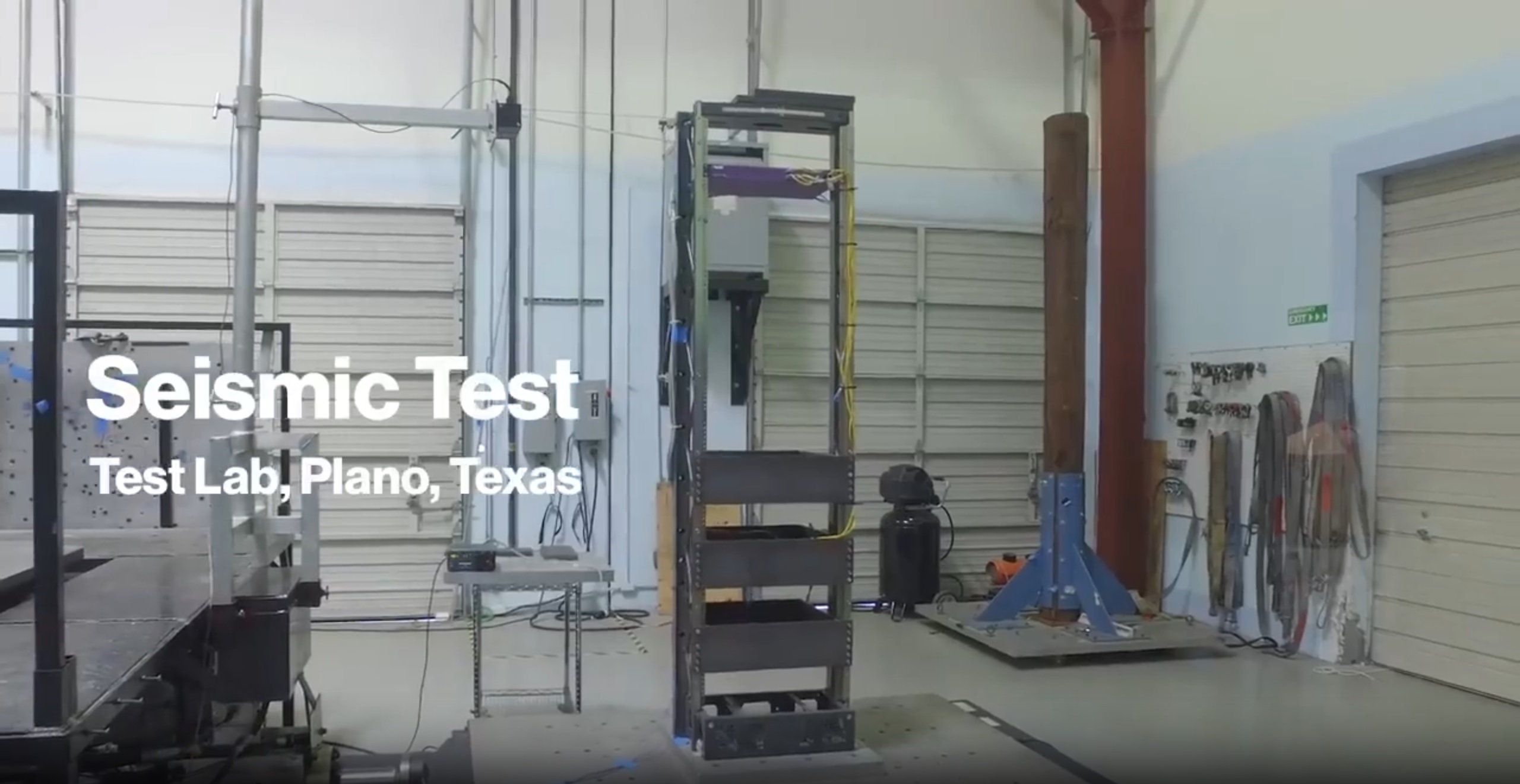
Verizon Seismic Test
Testing Software
The VibrationVIEW software can run earthquake vibration tests that meet the Telcordia standard and other earthquake time-history waveforms.
User-Defined Transient Software
Vibration Research controllers can run an earthquake test with the GR-63 transient time waveform using the VibrationVIEW Transient Waveforms Control software. The engineer can upload the time history data to the software, schedule several synchronous tests, and configure the SRS parameters.
Transient waveform control can be used for seismic testing or any industry where short-duration, high-amplitude transient events are likely to occur. It allows users to replicate time-history files and have better control over recorded events.
Modified Time-history Waveform
In VibrationVIEW, the user can make minor adjustments to the original time history file to meet or exceed the required response spectrum. The software can employ adaptive SRS control, so the user does not need to modify the wavelet table to compensate for structural resonances.
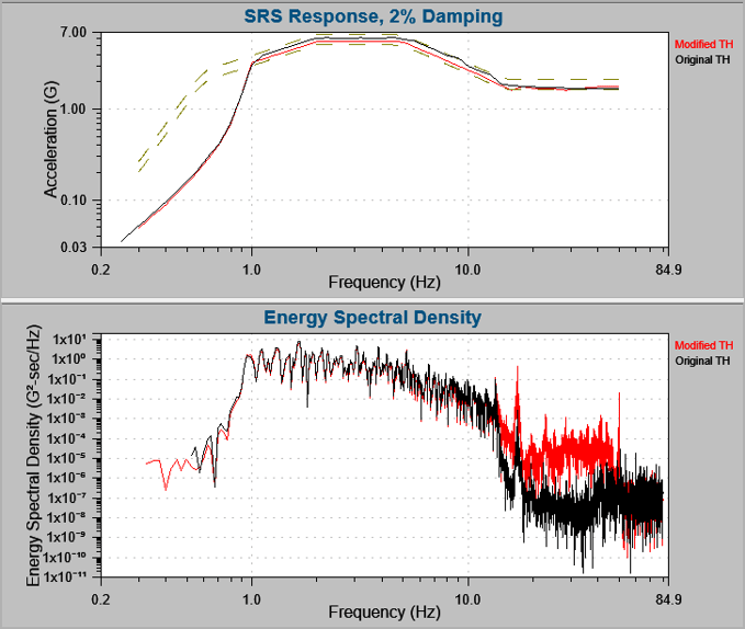
Modify a time history waveform to meet/exceed RRS.
Seismic Vibration Testing
The Telcordia GR-63-CORE standard provides a framework for validating telecommunications equipment against vibration-induced hazards such as handling shocks and seismic events. Rigorous test protocols and pre/post-test functional validation ensures that hardware remains fully operational even under extreme stress. Engineers can replicate GR-63 transient waveforms and evaluate performance with tools like VibrationVIEW. Compliance confirms structural and mechanical integrity and improves network reliability, especially in regions prone to earthquakes or transport-induced fatigue.
Interested in learning more about seismic testing with Vibration Research systems? Contact us!