Sensors are essential components when setting up a data acquisition system for field recording. If a sensor is in the wrong orientation, the recording device may gather incorrect data, if any at all. Additionally, parsing through data will be complicated if the engineer does not document the position or orientation of the sensors.
Pre-recording planning will help to simplify recording and analysis, especially if the engineer is recording at multiple locations. Although plans rarely pan out exactly as intended, it is wise to consider the behavior of the device under test and what vibration is necessary to record before getting it out into the field.
Preparation
It can be helpful to draw a preliminary diagram of the axes of vibration for the device under test. When the engineer gets to the field, this diagram can remind them how to orient their sensors and label them in the acquisition system. They should consider any surfaces they might wish to record, such as the undercarriage of a vehicle.
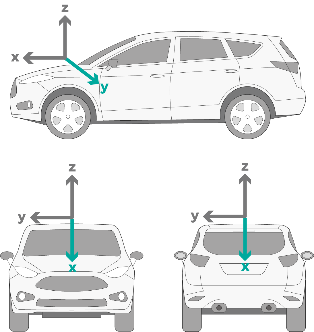
This type of diagram will help to keep axes consistent across recordings in different locations. Although engineers can label their axes differently at each location without affecting the data, the post-recording analysis will be challenging, particularly if comparing recordings at different locations.
Vibration Sensor Orientation
Single-axis Sensors
Engineers should mount single-axis sensors in the direction of the vibration they want to record. A single-axis sensor records data perpendicular to the mounting surface.
In the field, it is not always as simple as mounting the sensor in the direction of the excitation. A bump in the road may excite the suspension system in the z direction, but a window or mirror in the x direction. In the instance that the engineer doesn’t know which direction the component will vibrate, a triaxial accelerometer can be beneficial.
Triaxial Sensors
A triaxial sensor records data in the x, y, and z directions. The face of the sensor has x, y, and z labels that the engineer can use to align with their diagram.
Even if the engineer is recording data to determine the response axis of a component, it is still beneficial to be consistent with the axes across recordings. Post-recording, they will quickly know which axis it is vibrating on and can compare the response to other locations.
Adjusting Sensor Orientations in VR Mobile
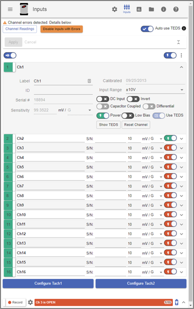
Inputs settings in VR Mobile.
Sensors typically have a designated face for mounting, so the engineer can only manually rotate two of the three axes. If the engineer cannot mount the sensor in the same direction as the axes they’ve diagramed, they can change the axes in the software.
For example, due to spacing constraints, a sensor might only fit so that the y-axis label records the z-direction data (and vice versa). The engineer can switch the axes in the software so that the z-axis data appears under a z-axis label and the y-axis data appears under a y-axis label. Otherwise, the engineer will need to note that the data labeled as y-axis is z-axis data, which can quickly become confusing.
Engineers can re-label their sensors manually in the Inputs tab in VR Mobile. VR Mobile is a desktop/mobile device application that works in tandem with the ObserVR1000.
Math Traces
The Math Traces feature in ObserVIEW also includes a solution for rotating triaxial sensor channels to a new direction. It can adjust the desired direction of motion per axis using the angle of the mounted sensor. To change the data for a single rotation about the axis, follow the instructions in the Uses for Math Traces in ObserVIEW document.
Invert
VR Mobile also has an Invert option under its Inputs parameters. If the engineer must mount their sensor upside down due to space constraints, they can select Invert to invert the sensor’s signal. Post-process, the positive and negative amplitudes will coincide with the typical orientation of the device under test.
Labeling
Adding the axis to the channel name will make for easier analysis later. VR Mobile simplifies this process if a sensor has a transducer electronic data sheet (TEDS). The user can select the Append Axes to Labels option under Inputs, and the software will add the axis to each channel name.
Sometimes, an x, y, or z-axis label is not as descriptive as a lateral, vertical, or longitudinal label. The engineer should use whichever is standard in their field, so long as they’re consistent.
Sensors Online Course
If you are interested in learning more about selecting and using sensors for proper vibration control, Vibration Research has a free online course on Sensors for Vibration Testing.