Nearly all vibration testing instrumentation is digital, but real-world signals are analog. Vibration control systems digitize the analog signals from the shaker table for processing. After processing, they convert the signals back to analog before outputting the drive signal to the shaker.
Most control systems condition analog signals before digitization. For example, many apply an analog anti-alias filter to minimize aliasing. As the name suggests, analog filters process analog signals (continuous-time signals).
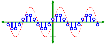
Sampling a sine waveform.
Control systems perform analog-to-digital conversion (ADC) after conditioning. Sampling is a standard method of ADC. Sampling takes measurements of a vibration waveform at regular intervals and structures them as a sequence of values, effectively converting a continuous-time signal into a discrete-time signal.
After sampling, the control system can perform signal processing on the data, including digital filtering. Digital filters process digitized signals (discrete-time signals).
To summarize, analog filters process analog signals from the shaker table before analog-to-digital conversion, such as sampling. Digital filters apply to digital signals after sampling.
Digital filters are more precise than analog filters, producing better results. They operate using numerical calculations, so they are not affected by component variations such as temperature change. Signal resolution is the primary limitation of their performance.
Digital Filtering in Frequency
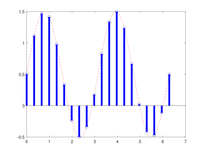
Input waveform before digital filtering in frequency.
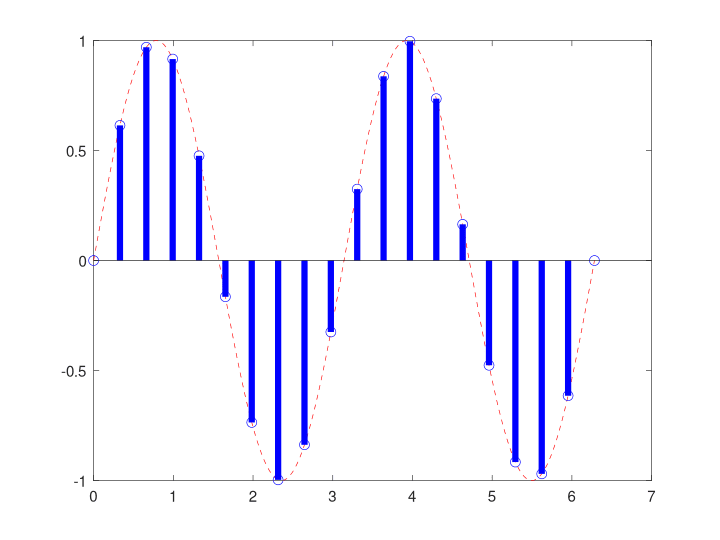
Output waveform after digital filtering in frequency.
Digital filters process discrete-time signals, meaning they operate on signals sampled at discrete intervals in time. However, vibration test engineers often implement digital filters in the frequency domain. Discrete-time signals can be represented in the frequency domain using techniques like the fast Fourier transform (FFT).
Vibration signals typically contain complex frequency content, including resonant frequencies, harmonics, and noise. Analyzing this frequency content helps engineers understand the system’s underlying vibration characteristics and target specific frequencies for filtering.
Many digital vibration filter designs selectively attenuate or amplify frequency components to achieve outcomes such as reducing noise or controlling resonance. Filters applied to frequency domain data use a frequency response parameter to shape the signal. Standard frequency responses include low-pass, high-pass, band-pass, and band-reject.
Digital Filter Architectures
Finite impulse response (FIR) and infinite impulse response (IIR) are two standard digital filter architectures. If you’d like to learn more about filter structure, we recommend enrolling in the Fundamentals of Signal Processing course at Vibration Research University.
Digital Filter Applications
Digital filters are typically software-programmable, and the various vibration test types necessitate filtering for different purposes. The following filtering video introduces digital filter applications for sine, random, and shock testing.
Three examples of digital vibration filters include:
- Sine Tracking Filter: isolates the pure sine tone so the controller can read its amplitude and control the test correctly.
- Random Notch Filter: rejects the response at specific frequencies to avoid over-testing at resonant frequencies while achieving the proper test levels.
- Shock Input Filter: removes significant high-frequency noise or low-frequency drift in the measurements.