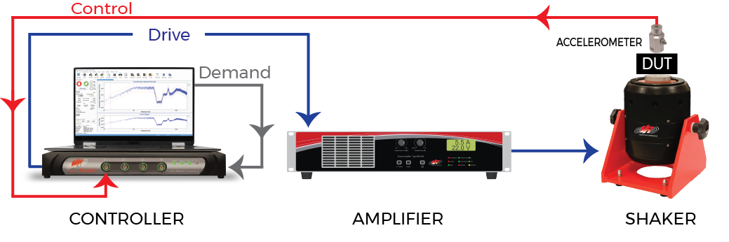
In vibration testing systems, the power amplifier supplies the power to drive the electrodynamic shaker. Similarly, servo-hydraulic shakers require a servo-amplifier [1].
The vibration controller outputs a simple analog signal that describes the amplitude and frequency of the vibration profile in terms of a rapidly varying voltage. This voltage signal cannot drive the shaker, so the power amplifier converts it to a high-level actuator current that can. Without this device, the control loop would essentially end at the controller’s output.
 The power amplifier’s function is straightforward; however, the device is necessary for vibration control, so engineers should understand its function. Supplying power to the shaker haphazardly can lead to product damage or employee harm.
Power Amplifiers for Shaker Control
Amplifier Gain
The power amplifier’s gain is an adjustable value, typically controlled with a knob on the front plate of the device. The gain determines the extent to which the amplifier boosts the analog signal. Turning the gain to 100% boosts the drive to the amplifier’s maximum capacity.
If a test is not running, reset the amplifier gain. If any question exists, shut down the amplifier. This action will ensure that power does not run to the shaker while the engineer sets up/adjusts the system. An unexpected power surge to the shaker can have dangerous consequences. Additionally, never change the amplifier gain while the test is running.
The amplifier gain differs from the system gain: a ratio of the accelerometer response (g) and drive voltage (V). Each device in the test setup—including the amplifier—affects the overall gain, which engineers use to determine the expected acceleration for a given voltage. Many drive limits, such as startup max system gain and startup max output consider the overall system gain.
What Amplifier Gain Value Should I Set?
With every new test setup, an engineer must determine the correct test levels, including amplifier gain. They want to provide sufficient power without causing unnecessary fatigue or damage. Typically, the amplifier manufacturer will recommend an initial gain level, such as the standard 70%.
From there, the engineer can determine the suitable amplifier gain by performing a system check before running the test and reviewing the projected levels during start-up.
In VibrationVIEW, the System Check mode verifies that the accelerometer, amplifier, shaker, and control system are functioning. Several System Check stop codes may indicate that the amplifier gain is too low, such as:
- No acceleration detected on Ch1
- Max system drive voltage
- Output signal clipping
The projected levels toolbar in VibrationVIEW provides additional diagnostic information about the expected results of a test during start-up. When the engineer starts the test in manual mode or schedules it at a lower initial level, the software can project the values for the lower level to each level in the test schedule.
If a stop code appears while running a test, the VibrationVIEW Help file will indicate if the amplifier gain is a likely issue. After the engineer has determined a suitable gain level, they should use the same gain settings each time they run the same test profile on the same test setup.
Should I Turn My Amplifier All the Way Up?
Running the test at full gain may be acceptable, but the suitable value is not always 100%.
Errors Related to the Amplifier
While the amplifier is an essential piece of equipment, it can be a source of error. Amplifiers are limited to their output voltage and current capabilities [2]. If the amplifier trips, it will display an error code on its front panel. Typical reasons include:
- Over-current
- Over-travel (displacement)
- Over-voltage
- Temperature sensors (overheat)
Amplifier Noise
The amplifier’s field supply or a ground loop can generate system noise. Additionally, the system may pick up on ambient noise between the controller and amplifier. While all power amplifiers distort the signal to some degree, a mindful test setup can minimize the impact of amplifier noise. To help prevent amplifier noise, engineers can:
- Ensure cables are shielded and not overly long to reduce the potential for electromagnetic interference
- Check the ground connections for the amplifier, shaker, and controller
Purchasing a Power Amplifier
 A vibration shaker and its amplifier must be powerful enough to drive the device under test and fixture to the test’s required force and motion levels. The shaker’s suspension must be sufficiently linear to reproduce the low-amplitude characteristics of the demand, and the amplifier’s noise floor must be low enough not to mask these features.
When choosing a power amplifier, engineers should consider the system’s overall power requirements, including overall mass and test specifications. Typically, they use the equation force = mass x acceleration for shaker sizing, but it also applies to the amplifier. The heavier the system, the more power it will need. Likewise, the higher the acceleration, the more power it will need.
A test’s power requirement increases as the shaker and amplifier performance degrades. Engineers may want to establish a baseline voltage, current, and temperature to monitor the amplifier’s performance over time. Power amplifiers have a typical lifetime of 15-20 years. The engineer should shut down the system for maintenance if the voltage exceeds a predetermined threshold value during a simple diagnostics test.
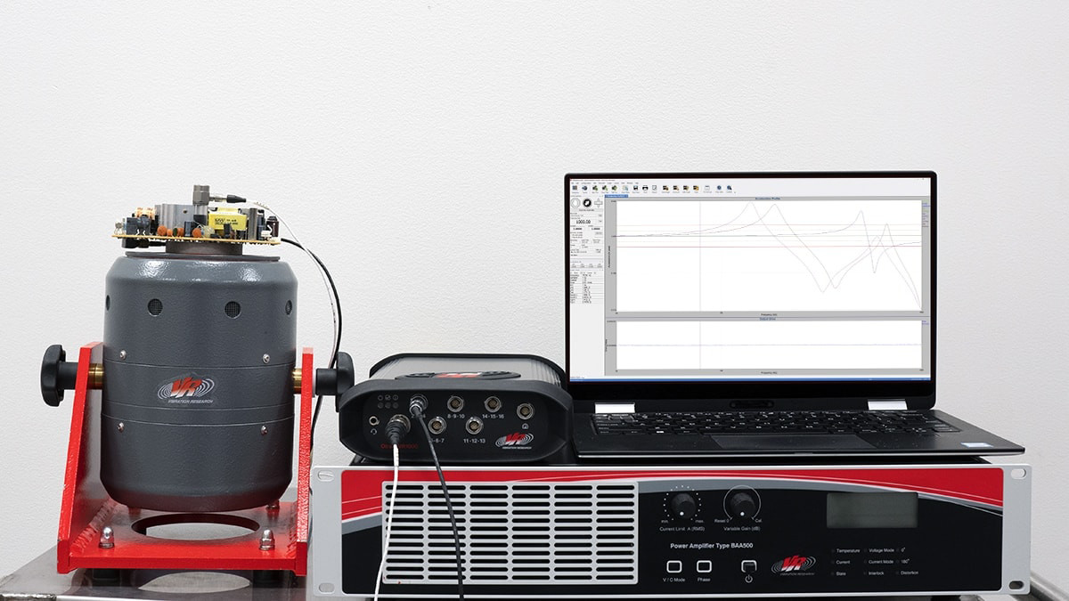
The electrodynamic shaker systems offered by Vibration Research consist of a shaker and a matching linear direct-coupled power amplifier. Customers can add additional components to the basic system to tailor it to specific needs. The systems have been designed and manufactured with both its shakers and matching amplifiers in tandem.
Integrating Modern Equipment into a Legacy System
 Vibration control systems are largely moving to digital processing, but many pieces of equipment still rely on analog signals. Most systems convert signals in the digital-to-analog (via a controller) to analog-to-digital (via an amplifier) path. Each conversion risks distortion and noise.
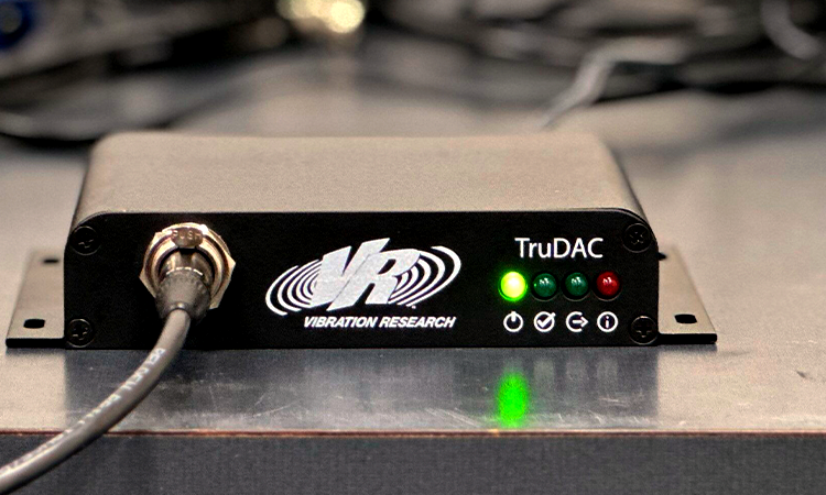
The TruDAC helps maintain a clean signal between a system’s vibration controller and amplifier, providing an isolated digital drive signal. (While the drive path is digital up to the TruDAC, it outputs analog for backward compatibility.) It also supports a direct digital interface for future amplifier upgrades. As amplifier manufacturers begin to support digital input directly, the TruDAC’s entire signal path will be digital, eliminating unnecessary conversions.
The TruDAC has two ±10 V analog outputs that are compatible with most vibration amplifiers. Its digital interface preserves existing investment and paves the way for full digital amplifier integration.