Article Overview
- Explanation of strain gauge devices
- Descriptions of bonded metallic strain gauge and reusable piezo-resistive transducers
- Necessity of a signal conditioner
- Wheatstone bridge configurations
- Definition of gauge factor
- Impact of temperature on strain measurements
Strain measures the deformation of an object due to an applied force. Normal strain (ε) is a ratio of the material’s change in length to the original. Tensile strain due to elongation is a positive value, and compressive strain due to contraction is negative.
(1) 
What is a Strain Gauge?
Strain-sensitive materials have an electrical resistance proportional to strain and include metals such as foil/wire and semiconductors. A strain gauge (or gage) uses the material’s change in resistance to measure strain.
A strain gauge includes a strain-sensitive material and can be the active element in a transducer or attached directly to the device under test [2].
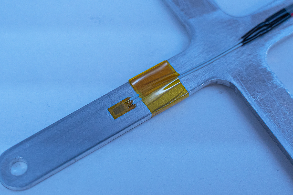
A bonded strain gauge.
The bonded metallic strain gauge is a popular choice for stress analysis because of its versatility. It is composed of metallic wire/foil in a grid pattern bonded to a carrier. A bonded strain gauge is often part of a larger circuit configuration to accurately measure the small changes in resistance.
Reusable Strain Gauges
Another option for measuring strain is the piezo-resistive transducer, whose electrical output depends on the deformation of its semiconductor resistive element. It is typically more resistant to change than a wire strain gauge transducer for a given deformation; therefore, it might only measure dynamic, not static, strain.
Reusable strain gauges, such as the PCB Model 740B02, measure dynamic strain but require less time to set up than bonded ones, as they do not need a circuit arrangement. The following video demonstrates the ease of setup using the ObserVR1000 data acquisition hardware.
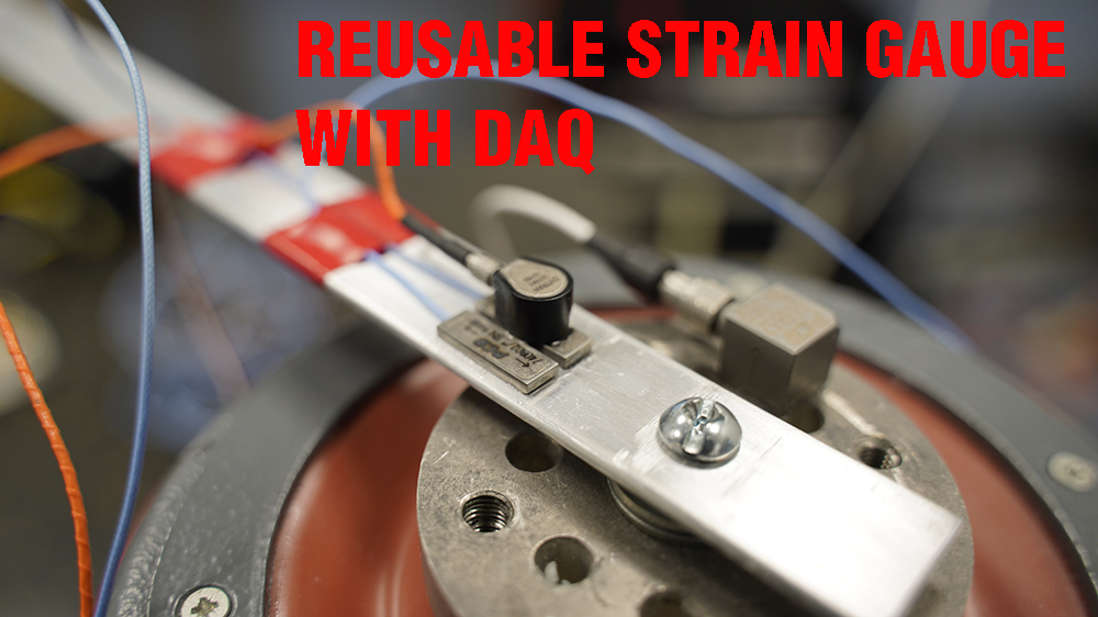
Choosing between a bonded strain gauge and a piezo-resistive transducer will depend on the application, resources, and preciseness required of the data.
Powering a Strain Gauge
A strain gauge requires electrical amplification and a steady current source. Its output is usually too low (<10mV) for accurate measurement. Strain gauges do not have integrated electronics for amplification and instead rely on an external piece of equipment.
A signal conditioner supplies a constant voltage to the strain gauge, as the transducer does not self-generate power [1]. The excitation voltage is usually 3V or 10V and must be stable and regulated to avoid measurement error.
The conditioner also applies filters to limit the output signal’s bandwidth to the frequency range of interest. Amplification and signal conditioning help ensure an accurate output measurement with minimal noise.
Circuit Arrangement
Strain gauges can be arranged in a circuit for greater versatility. The circuit is wired to the signal conditioner, and it supplies the strain gauge with the excitation current and receives the output signal.
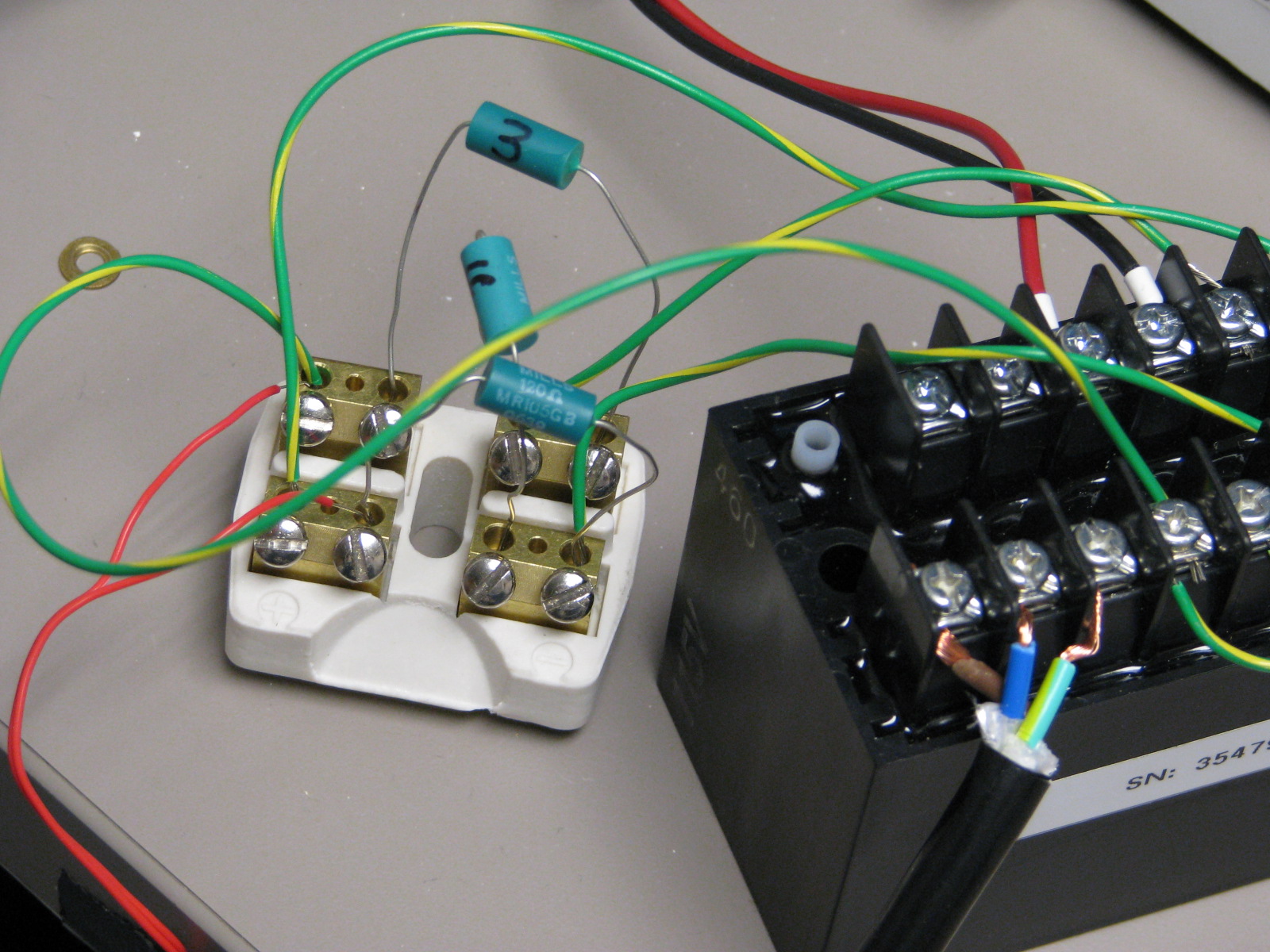
A bridge arrangement for a strain gauge.
Wheatstone Bridge
The Wheatstone bridge is the most common circuit arrangement because it is a precise method of measuring resistance. It consists of four resistive arms in a square formation, an excitation source, and a voltage detector.
Electrically, the Wheatstone bridge is composed of two voltage dividers, and it is assumed to be balanced (zero output voltage) when no strain is applied. This arrangement provides a reference voltage, allowing the bridge to measure resistance indirectly as a change in output voltage [4].
The simplest Wheatstone arrangement has one active strain gauge, although it can include multiples for various purposes. The number of active gauges determines the circuit’s configuration type: quarter-bridge, half-bridge, or full-bridge.
A Wheatstone bridge is favorable because it can be adjusted to compensate for temperature and transverse sensitivity and reject/augment certain strain measurements.
Static Offset
Theoretically, a Wheatstone bridge circuit is balanced when no strain is applied, meaning its output is 0V. In a practical application, some activity will generate a nonzero initial offset voltage. Potential voltage sources include resistor tolerance, variations in resistance, lead wire resistance, and strain from the gauge positioning.
There are also static—meaning unchanging—measurements while the test runs. Strain can be dynamic or static depending on how quickly its values change. Engineers seek the DC (steady-state) portion of the output voltage for precise measurements. For a dynamic application, they may only need to measure the fluctuating component.
The VibrationVIEW software compensates for DC voltage offset by adjusting it to a 0V value. To view the offset, the user can enable the DC inputs option, which disables all low-frequency filtering. In Sine, they will also need to turn off any tracking filters for the channel measuring strain.
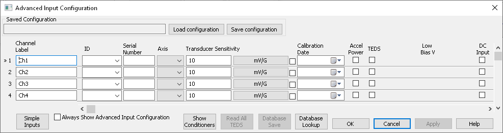
DC inputs option in the Advanced Input Configuration dialog.
If the DC inputs are enabled, the user can balance the initial offset with the AutoZero command, which resets the levels of the inputs configured as DC reading to zero.
Parameters
Gauge Factor
The gauge factor is a quantitative measure of a strain gauge’s sensitivity to strain. It is a ratio of the fractional change in resistance to the fractional change in length.
(2) 
The sensor documentation will include the sensor’s gauge factor value. It is usually between 2 and 4 for metals and anywhere from 50 to 200 for semiconductors. Larger gauge factor values are desirable because greater changes in resistance—and thereby sensitivity—lead to a higher voltage output.
Temperature
Temperature can directly affect the gauge factor. The strain gauge measures any change in resistance as the result of strain [2]. If the environmental temperature causes thermal expansion of the strain-sensitive material, the sensor will interpret the change as mechanical strain. Therefore, it is necessary to document the temperature of the test environment.
Static or quasi-static-type strain signals are more sensitive to temperature changes.
Application in VibrationVIEW
Strain gauges must be conditioned correctly before connection to a VR hardware input, including a bridge and a differential amplifier. Then, the user can connect the conditioned strain gauge to the desired channel.
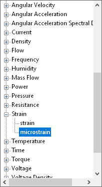
Strain unit options.
The gauge factor is dimensionless, so the sensitivity must be calculated in mV/engineering units. The VibrationVIEW software includes strain and microstrain as input configuration units. You will need the gauge factor, bridge type, and excitation voltage to convert to mV/strain or mV/microstrain.
Some full-bridge systems, such as load cells, will provide an mV/V rating, which is the mV output per volt of excitation at the gauge’s full output. To calculate mV/strain or mV/microstrain, you will need the excitation voltage and capacity of the sensor.
Conclusion
A strain gauge uses a material’s change in resistance to measure strain, which engineers use for stress analysis. There are many strain gauge options to choose from, and the main driver behind the selection is the testing application. Bonded metallic gauges offer versatility across applications, while reusable transducers facilitate rapid dynamic measurements.
Additional hardware is also necessary for conditioning and acquiring measurements, including a signal conditioner, power supply, and cables (such as BNC to wire). Accurate strain gauge readings rely on stable excitation from signal conditioners and precise configuration in Wheatstone bridge circuits for sensitivity and compensation. The gauge factor quantifies sensitivity, and temperature effects must be considered to maintain measurement integrity. Altogether, these principles lend to reliable, high-fidelity strain measurements, essential for engineering analysis and structural diagnostics.
Online Sensors Course
![]() Interested in learning more about sensors for vibration testing? Enroll in the free VRU course for lessons on sensor types, specifications, and applications.
Interested in learning more about sensors for vibration testing? Enroll in the free VRU course for lessons on sensor types, specifications, and applications.