Over the years, we have worked alongside many customers to address the challenges of vibration testing. While some concerns are more atypical than others, there are several common problems our customers come across. Luckily, their solutions are relatively simple. Below, we have listed five common vibration test issues and their potential solutions.
See also: Why Vibration Testing?
NOISE FLOOR
The Problem
From the hum of a fan in the computer to the conversations of others in an adjacent room, background audio noise is prevalent in our day-to-day lives. Generally, we refer to these various background sounds as “white noise.”
The same background noise is also found in digital circuits and is known as the “noise floor.” The noise floor can conceal important resonances if the acceleration levels are similar. The following items can contribute to the noise floor:
- Ground loops/60 cycle noise
- External EMF noise
- Circuitry noise (shot noise of P-N junctions; thermal noise)
Figure 1 illustrates the background noise floor during a vibration test.
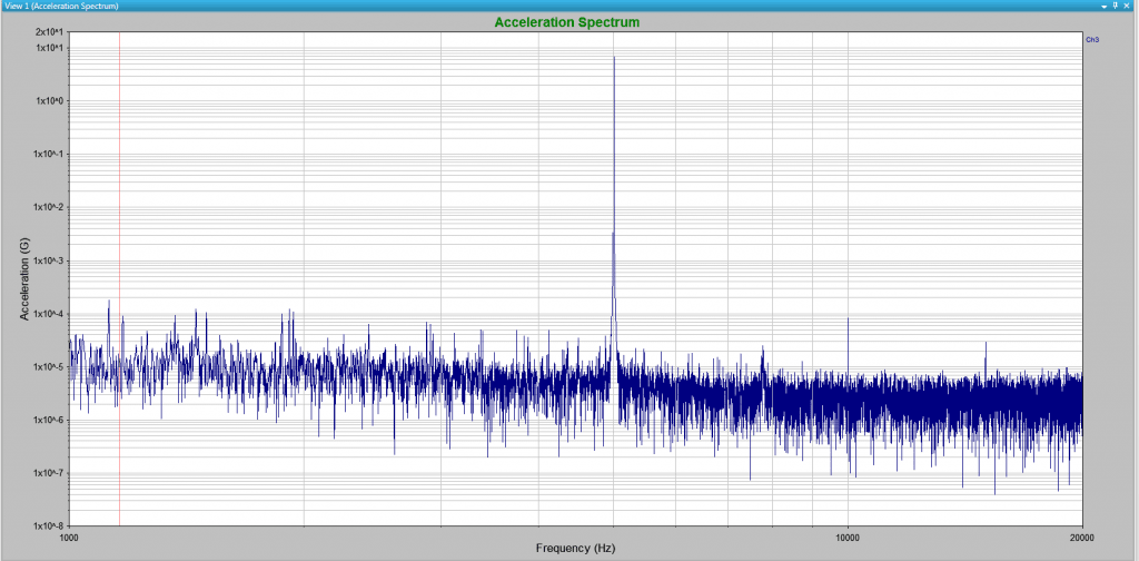
Figure 1: Noise floor across a spectrum from 1 kHz to 20 kHz. Several resonances stand out above the noise floor. The resonances near 5 kHz are easily identifiable, whereas the resonance near 15 kHz stands just above the noise floor.
The Solution
While the complete removal of noise is nearly impossible, noise can be reduced. Two relatively simple solutions to minimize noise and thereby reduce the noise floor are:
- Remove ground loops
- Use high-quality components in your circuit boards
ACCELEROMETER SENSITIVITY ISSUES
The Problem
Many problems related to transducers can arise. As a result, a test may fail or poor results may be obtained. Several common issues include:
- Incorrect sensitivities
The sensitivity values for the transducer must be entered correctly when setting up a test. For example, suppose an accelerometer is calibrated to 10 mv/G but the test engineer mistakenly enters the sensitivity as 100 mv/G. If the accelerometer detects a 10 mV value, it will display a 0.1 G acceleration value rather than a 1 G acceleration. As a result, the data will be off by a factor of 10. The difference in this example is drastic, but even a slight deviation from the certified value can lead to an error, albeit small.
- No power to the accelerometer
Many accelerometers require external conditioning or power from an external source. The accelerometer will not perform a reading if it is not connected to a power source. This is an easy fix, but a rather common error! It is akin to turning on your computer but neglecting to plug it in. When a computer is unresponsive, it is always wise to check the power cord. The same can be said for an accelerometer.
- Improper accelerometer for the test
Another common accelerometer-related problem occurs when an improper accelerometer is selected. For example, suppose a controller has a 5 V max input. If a 100mV/G accelerometer is used in conjunction, the accelerometer will saturate with a high-Q resonance that measures greater than 50 G. As a result, the accelerometer will be unable to collect data above 50 G.
The Solution
- Use TEDS (transducer electronic data sheets)
- TEDS are stored in the memory of the IEPE accelerometer. The calibration data and characteristics of the accelerometer, such as its calibrated sensitivity, calibration date, serial number, manufacturer, and calibrated frequency range, are stored in the memory of the IEPE accelerometer. This information can be imported to the controller software so incorrect sensitivity values cannot be entered.
- Select a different sensitivity accelerometer
- Engineers must select accelerometers based on the circumstances of the test and make sure the accelerometer will not be saturated.
CABLE ISSUES
The Problem
Vibration tests can develop issues and supply poor results due to problems with the cables.
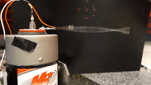
- Cable Whip
- When a cable is not properly secured, it can vibrate wildly due to the vibrations of the test. This whipping action can introduce additional noise-like data to the results (triboelectric effect).
- Cable not connected securely to the accelerometer
- Cable connection issues can lead to discontinuities in the data.
The Solution
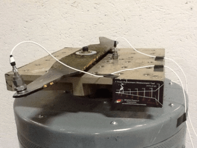
- Secure the cables
- Cables should be secured so they cannot whip during a vibration test. Electrical tape is commonly used to secure any cables in position.
- Properly connect cables
- Cables must be tightly fastened to the accelerometer. Care must be exercised to make sure the cable is fastened to the accelerometer and the cable pin is not bent or damaged.
ACCELEROMETER MOUNTING ISSUES
The Problem
Problems during vibration testing can occur if the accelerometer or transducer are not properly mounted to the device under test (DUT). Valid data cannot be obtained if the accelerometer is not mounted properly. Two common sources of improper mounting are:
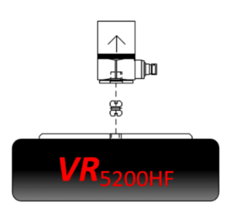
- Mounted in the wrong direction
- Mounting an accelerometer in the wrong orientation happens more often than you might expect. A single-axis accelerometer may measure an accelerometer in the vertical plane. However, an engineer may be using a shaker that vibrates in the horizontal plane (slides back and forth). If the accelerometer is mounted as if measuring vertical motion, the data obtained (if any) will not make sense or will be unusable.
- Not securely mounted
- The stud mount method is the best method of mounting an accelerometer. Sometimes, however, the stud mount method is not available and an adhesive is used instead. Cyanoacrylate glue is the next best method, but engineers sometimes settle for a wax adhesive because of convenience. Wax adhesive can lead to poor contact between surfaces, especially under certain temperatures, and consequently, result in a poor collection of data.
The Solution
- Confirm the accelerometer is in the correct orientation
- Engineers should confirm the direction that the accelerometer uses to measure acceleration and mount the accelerometer in the correct orientation.
- Mount with the best possible mounting method
- Engineers should use the best mounting method for the accelerometer. Do not use the most convenient method if it is not also a method that produces satisfactory results.
Resource: Accelerometer Mounting Tip Sheet
AMPLIFIER ISSUES
The Problem
Other common errors in vibration testing are associated with the amplifier.
- Gain Cranked Up
- It can be very dangerous if a test engineer adjusts the equipment when the amplifier gain is cranked up. Test engineers should always turn down the gain on the amplifier in-between tests. When the gain is turned down, no significant current can be sent to the shaker even if the current rises rapidly to the amplifier/shaker. This can prevent a damaging blow to the shaker.
- Gain Off or Dialed Down
- Before running a test, turn on the amplifier and turn up the gain (if necessary). Forgetting to do so will result in some error message.
The Solution
- Turn down the gain
- Whenever a test is not in progress, and especially when an engineer is adjusting the test set-up and cabling, the amplifier gain should be turned down. This will prevent any damage to the shaker system.
- Turn on the gain and turn it up
- When the test is ready and no more adjustments will be made, turn on the gain and turn it up.
Have any additional questions? Our support team is ready to help!