Do you perform vibration testing on products containing electromagnetic relays or motor contactors?
If so, there is the possibility that a vibration event will cause chatter in your electromagnetic relay. Vibration Research’s VibrationVIEW software offers a chatter monitoring package that detects and measures relay chatter events.
Vibration Research’s chatter monitoring capabilities are helpful in many testing situations, including:
- Seismic vibration testing of a product containing relays or motor contactors
- Identifying possible discontinuities in relays
- Evaluating the acceptance criteria for relays (IEEE 501; ANSI C37.98)
Background
Mechanical relays and contactors are essential components in many electrical systems. They are designed to allow for low voltage control of a high voltage system. This design gives electricians and technicians the ability to control an array of electrical components without needing to run medium or high voltage lines.
Either DC or low voltage AC can control the switching of a mechanical relay and essentially act as a switch to turn the power on or off to the connected equipment. Figure 1 shows a typical relay configuration; Figure 2 shows a typical contactor configuration.
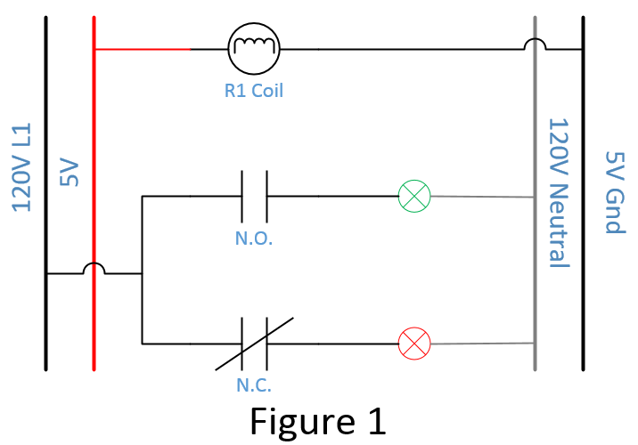
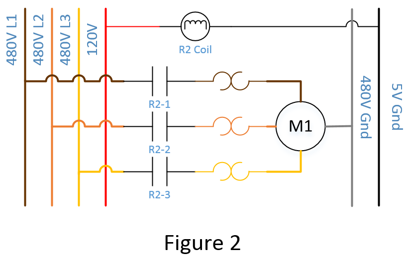
Figure 1 shows a typical setup for a single-pole, double-throw (SPDT) mechanical relay, which consists of two contacts: normally open (N.O.) and normally closed (N.C.). If the 5V line does not have power applied, the red indicator will be ON and the green indicator will be OFF. When power is applied to the 5V line, the R1 coil (an electromagnetic coil) is energized, thus switching the positions of the two contacts. The N.O. contact will close, and the N.C. contact will open. This action will energize the green indicator and de-energize the red indicator.
In Figure 2, a single relay coil controls all three contacts. When the coil is energized, R2-1, R2-2, and R2-3 will close, and the motor will start. When power is removed from the coil, all three contacts will open, stopping the motor. In each case, the electromagnetic coil (R1 or R2) changes the position of the relay, allowing the technician to control the operation of the connected devices.
What is Relay Chatter?
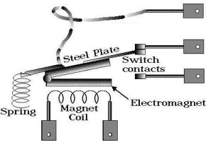
Figure 3. Typical electromagnetic relay.
A generic relay consists of a switch that is operated by an electromagnet (Figure 3).
Vibration events or resonance can cause the steel plate to disconnect momentarily from the switch contacts. In the case of a large, shock-like vibration (pot-hole, earthquake, etc.), the mass on the end of the spring may jerk down and then rebound upwards, momentarily forcing the steel plate to separate from the N.C. switch contact.
Similarly, if the electromagnet is activated, and the steel plate is in contact with the N.O. switch contact, a large vibration may be strong enough to overcome the magnetic attraction between the steel plate and the electromagnet, causing the steel plate to separate momentarily from the N.O. switch contact.
Types of Chatter Events
Chatter events can be classified as a discontinuity or bounce.
Discontinuity is a significant deviation from a monitored parameter.
Bounce is an event where the N.O. contact does not make a secure connection immediately after the electromagnetic coil is energized. If the current draw overloads the contacts after the coil is initially energized, then a perpetual bounce cycle may be started, where there are several moments of contact and loss of contact.
This type of chatter event can cause severe damage to the contacts because the electrical charge will jump across the short gap between the contacts, causing extra wear and damage. Contact bounce is a common problem in motor contactors that are not appropriately sized for the equipment.
Chatter Due to Vibration
Chatter caused by vibration is another event technicians must evaluate. If the relay or contactor is subjected to a large shock event, such as an earthquake, the electromagnetic coil holding the contacts in the energized position and the spring tension holding the contacts in the de-energized position must be strong enough to withstand the force of the event.
Technicians can recreate this chatter event in a laboratory setting by mounting the relay or contactor as suggested, running a shock test or earthquake simulation, and monitoring the state of the contacts. Any change in the voltage for an N.C. or N.O. contact indicates a chatter event. The technician can then evaluate these events to determine the effectiveness of the contact in the case of an earthquake or other shock event.
Software for Monitoring Chatter Events
The VibrationVIEW software includes a Chatter Monitor add-on package capable of detecting chatter events. VibrationVIEW uses the RecorderVIEW package to record the inputs throughout a test. The software then evaluates the recording to determine if a relay chatter event has occurred.
At the completion of this evaluation, a dialog box will appear that shows each event that was detected, allowing the technician to evaluate each event. Upon completion, they can create a chatter report for each event. Recorded files (.vfw) can also be processed using the Chatter Monitor software.
In the example below, a recorded file is post-processed using the Chatter Monitor software in the Shock test module (Figure 4). To evaluate the data:
- Select the Chatter Tab
- Select the Enable Chatter Monitoring checkbox
- Select the channels to evaluate
- Set the contact type for each channel
- Configure the remaining settings with chatter criteria
- Select Evaluate File
- Open the recording to analyze
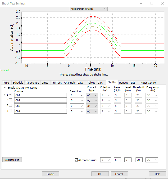
Figure 4. Chatter Monitor add-on in the Shock test software.
After the software has analyzed the file, a dialog box will appear displaying the detected chatter events and a Pass/Fail evaluation based on the criteria set in the chatter tabs of the test profile (Figure 5).
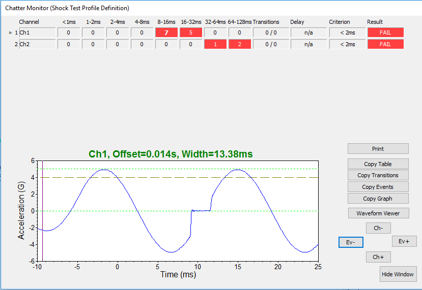
Figure 5. Chatter Monitor dialog in the VibrationVIEW software.
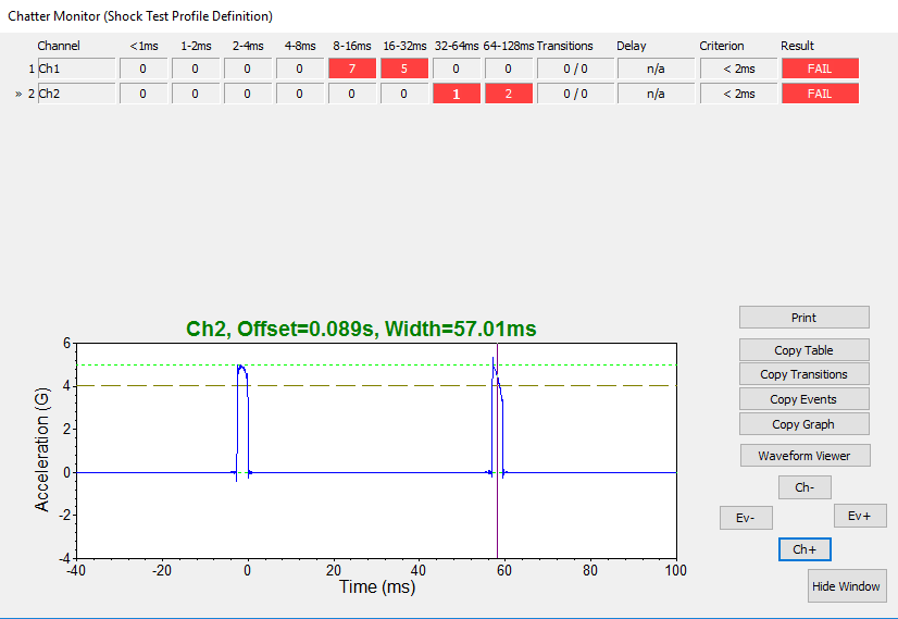
Figure 6: Chatter Monitoring Results for Channels 1 and 2.
Select the Ch + and Ch – buttons to change the channel in the graph window. Ev+ and Ev- cycle through the detected events (Figure 6).
With VR’s VibrationVIEW software and controller, you can detect, measure, and monitor chatter events that may occur during vibration tests that include relays or motor contactors.