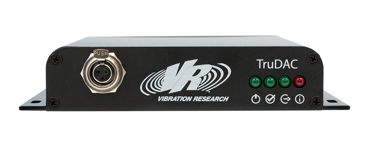
The TruDAC (true digital-to-analog) is a digital drive interface that replaces traditional analog drive connections. TruDAC simplifies, isolates, and future-proofs your vibration system. Wondering how TruDAC can improve your system setup? The following article highlights several key uses of this drive interface.
TruDAC Uses
- Amplifier safety
- Modern equipment integration with legacy system
- Long cable runs between controller and shaker
- Ground loops in complex equipment setups
- Electrical interference
- High-frequency testing
- Precision vibration testing
Amplifier Safety
Amplifiers operate at high voltages and currents and create strong electromagnetic fields. Laboratories require safety precautions to protect operators and test articles.
With built-in protections, the TruDAC is a safer alternative to analog BNC drive cables. If the TruDAC signal is compromised, the analog signal is safely disconnected from the amplifier, while an intermittent BNC analog drive cable may damage your shaker.
For example, if an operator disconnects the TruDAC cable while the amplifier gain is active, the analog is immediately disabled. Parity detection identifies errors, and heartbeat auxiliary data communication channels ensure signal integrity, delivering a valid signal to safely disconnect any analog interfaces.
The TruDAC also eliminates intermittent analog signals, which can create large transients. The TruDAC will shut down the amplifier output if the signal is disconnected and only restores it after the signal is shut down.
TruDAC implements the IEC958 standard for professional electrodynamic amplifier applications.
Modern Equipment Integration with a Legacy System
Vibration control systems are largely moving to digital processing, but many pieces of equipment still rely on analog signals. Most systems convert signals in the digital-to-analog (via a controller) to analog-to-digital (via an amplifier) path. Each conversion risks distortion and noise.
The TruDAC helps maintain a clean signal between a system’s vibration controller and amplifier, providing an isolated digital drive signal. (While the drive path is digital up to the TruDAC, it outputs analog for backward compatibility.) It also supports a direct digital interface for future amplifier upgrades. As amplifier manufacturers begin to support digital input directly, the TruDAC’s entire signal path will be digital, eliminating unnecessary conversions.
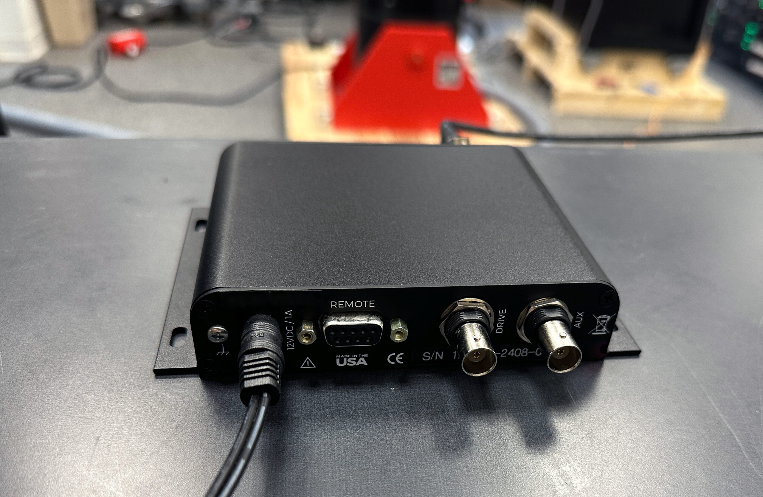
The TruDAC has two ±10 V analog outputs that are compatible with most vibration amplifiers. Its digital interface preserves existing investment and paves the way for full digital amplifier integration.
Long Cable Runs Between Controller and Shaker
Many vibration control systems rely on analog drive paths that convert digital signals to analog and re-digitize them via the amplifier. Analog circuits are susceptible to noise interference and signal degradation, particularly over longer distances and higher frequencies.
Short cable runs, while recommended, are not always practicable. Test facilities may have a remote amplifier room or a separate control bay, such as in larger facilities or those with environmental chambers with remote racks.
The TruDAC’s digital drive path and XLR (balanced) digital signals support longer cable lengths between the amplifier and controller while avoiding control signal degradation. It provides a clean, isolated digital drive signal that is less susceptible to interference. Cable lengths of 100+ m (328 ft) between the controller and the TruDAC digital input are possible with the appropriate 110-ohm AES/EBU cabling.
What to Look for
- Signal quality degradation when amplifier is far from controller
- Performance improvement with shorter cables
- Sensitivity to cable routing near power lines
Ground Loops in Complex Equipment Setups
Not every system with an amplifier experiences a ground loop, but engineers should consider ground potential when designing even a basic control system. As systems become more complex, the possibility of a ground loop increases because additional electrical equipment introduces potential ground paths.
Vibration systems integrated with equipment like thermal chambers, hydraulic systems, or auxiliary data acquisition systems are more susceptible to ground loops due to multiple chassis grounds. Ground loops pick up interference currents, creating electrical noise.
The TruDAC’s transformer-coupled digital input separates ground references operating at different potentials, and its analog outputs are fully isolated from ground. The TruDAC breaks the ground path between the controller and the amplifier, preventing ground loops and electrical noise.
What to Look for
- Intermittent and unexplained signal offsets
- Noise that corresponds to changes in equipment grounds
- Measurable potential difference between controller and amplifier chassis
- System behavior change when using different outlets
Electrical Interference
In most cases, electrical noise in a vibration control system originates from two primary sources: ground loop noise and electromagnetic interference (EMI). Electrical interference can result in unexplained signal noise or unstable drive levels. Similar to ground loops, complex equipment setups with multiple high-power electrical systems increase the potential for electrical interference.
Vibration testing systems are susceptible to EMI from equipment or external sources. Long or poorly shielded cables, some electronic components, and vibration amplifiers may inadvertently function as antennae, capturing EMI and channeling it into the system. Proper grounding techniques, cable management, and high-quality shielding help minimize EMI and thereby maintain test reliability.
The TruDAC addresses EMI challenges by breaking potential ground loops and supporting longer cable runs. Its digital drive interface reduces the possibility of electrical interference coupling into an analog circuit. Its balanced 110Ω XLR transmission rejects EMI common in test labs and high‑power shaker systems.
What to Look for
- Elevated noise floor in low-level tests
- Hum or broadband noise on analog drive signals
- Noise that corresponds to power status of nearby equipment
High-Frequency Testing
Analog circuits are susceptible to noise interference and signal degradation, particularly over longer distances and higher frequencies. High-frequency signals increase the possibility of electromagnetic interference, even in systems with short cables. Signal degradation and noise affect the accuracy of the signal amplitude.
Engineers running high-frequency testing may have more difficulty controlling interference that affects test results. The TruDAC offers improved high-frequency noise immunity. It uses balanced differential signaling over twisted-pair cabling to minimize EMI and crosstalk.
What to Look for
- Difficulty maintaining control at upper frequency range
- Signal attenuation at high frequencies
- Increased distortion during high-frequency sine sweeps
Precision Vibration Testing
Vibration test profiles can have tight tolerances, particularly in aerospace and defense industries. High-frequency sine or sine-on-random qualification tests leave little room for error, necessitating a clean signal with accurate measurements.
The TruDAC’s AES3 digital audio interface delivers a deterministic, bit‑accurate signal path designed for the precision demands of vibration control and signal acquisition. It provides a continuous, real‑time data stream with no buffering uncertainty or retransmission layers.
This deterministic transport ensures that high‑resolution audio and control signals reach the TruDAC exactly as generated without timing jitter or artifacts. For environments where data integrity and timing accuracy impact control performance—such as closed-loop vibration testing—the TruDAC ensures consistent and uninterrupted delivery every time.
What to Look for
- Aerospace or automotive tolerances difficult to maintain
- Unexpected notching behavior
- Slight but repeatable deviations from specification limits