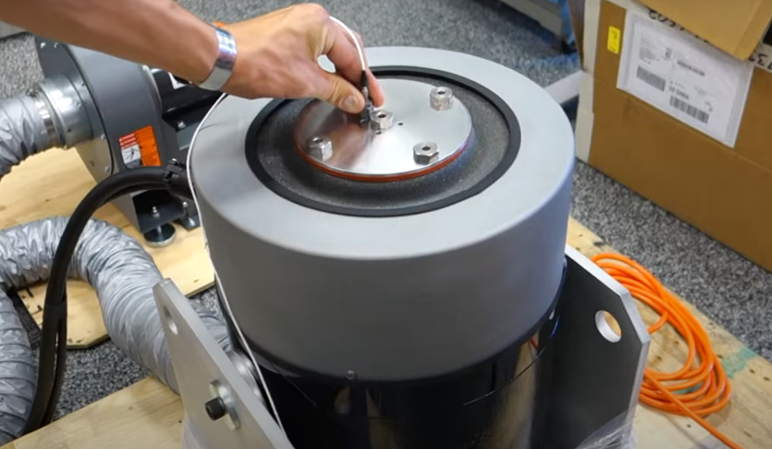
The control accelerometer is critical to maintaining safe amplitude levels during a vibration shaker test. It indirectly controls/limits the vibration levels that the system experiences during testing.
For example, if the accelerometer is mounted at a point with minimal vibration (such as a node), it will measure lower amplitudes, leading to an underestimation of the structure’s response. The location can also influence the frequency measurement, potentially misinterpreting the structure’s dynamic behavior. If the accelerometer is mounted at a highly damped point, it might indicate a higher energy dissipation than more dynamic regions.
Article Overview
- Role of the control accelerometer in closed-loop vibration testing
- Explanation of resonance in the control system
- Importance of establishing an operating baseline to identify resonant behaviors
- Guidance on choosing sensor location
- Overview of multi-point control setups
- Best practices
Control in Closed-loop Systems
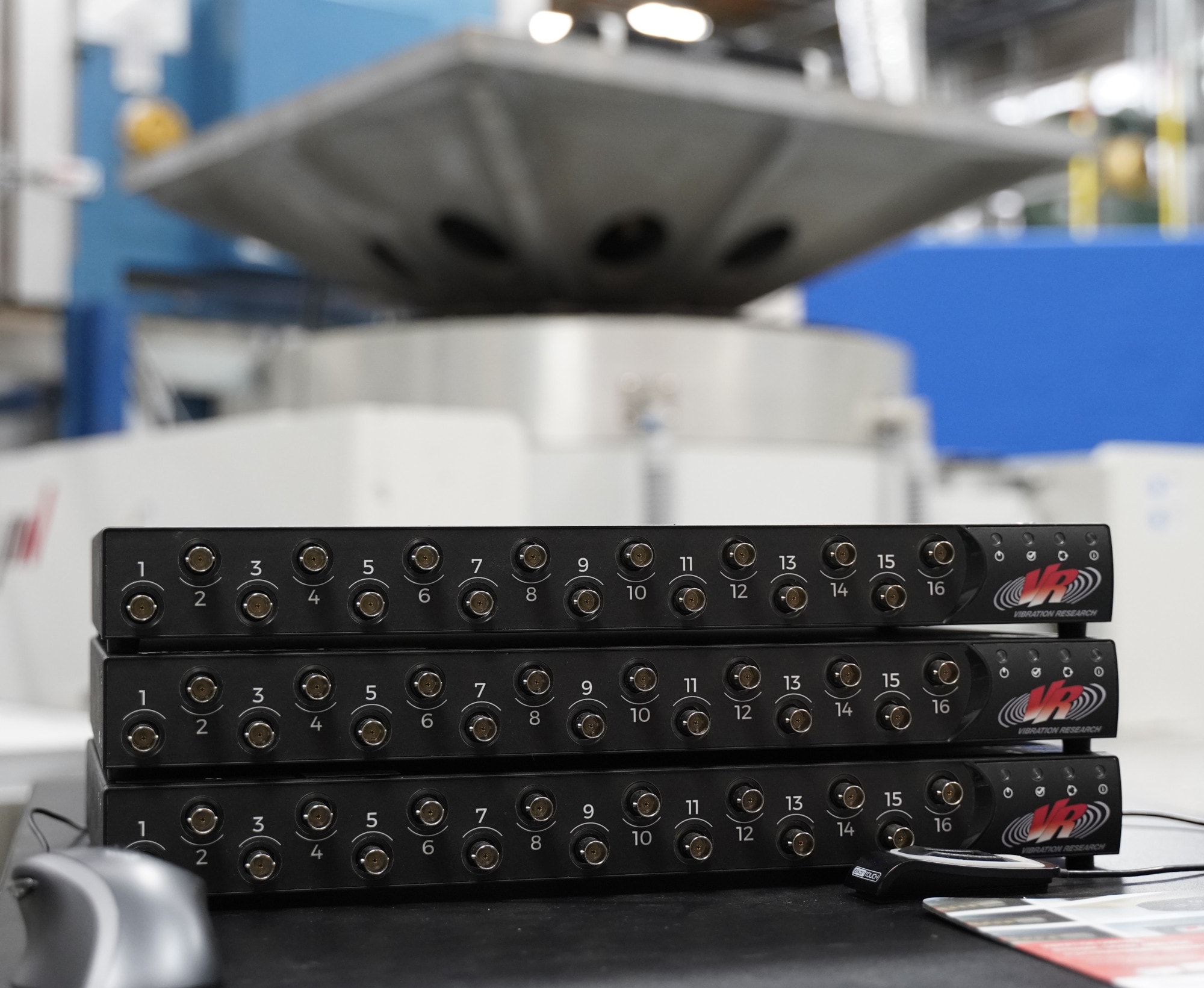
 A basic vibration control system runs in a loop consisting of a drive and response signal. The drive signal instructs the shaker to vibrate at x acceleration (or velocity, displacement, etc.), and the control accelerometer measures the system’s response amplitude. If the drive and response signals differ, the controller adjusts the drive to maintain the user-defined amplitude.
A test system controls amplitude levels solely at the control accelerometer(s). The placement of these sensors can affect the test results, and their correct placement can prevent over/under-testing and system damage. Engineers seek to mount their control accelerometer in the proper location for their test setup to protect their equipment and achieve reliable results.
This article will discuss where to mount a control accelerometer when running a single-axis vibration test based on engineering experience.
Everything Resonates
Before running a vibration test, we must consider that everything resonates at some frequency. In a laboratory, a test profile can match the resonant frequency of the floor, fixture, component, etc., amplifying levels to a potentially dangerous range.
While some vibration tests run until the DUT breaks, an engineer never intentionally sets out to damage their shaker fixture because it is costly and dangerous. In other scenarios, the DUT may be expensive/volatile, and the engineer must take caution not to over-test. In any situation, the control accelerometer is as important for protecting the shaker fixture as for the device under test.
Operating Baselines
 Test engineers should understand the mechanics of a system’s components and how they might impact the outcome of a test. The Determine Operating Baseline lesson on VRU lists several tests that engineers can perform to determine the operating baseline of their shaker system, including a low-level sine sweep to identify resonances. Component resonant frequencies can change based on configuration, and the lesson suggests running the baseline operating tests in several system configurations.
Control Accelerometer Location & Test Results
The effect of the position of the control accelerometer on the test results should be negligible but can be significant. Its position determines, in part, the vibration levels that drive the system; therefore, it can affect the test results to varying degrees.
Engineers must consider the vibration behavior at different locations on the fixture, particularly if the test setup is complex. In general, the sensor location should represent the overall behavior of the system; if it’s too localized, it might not capture the full dynamics of the system.
However, the engineer must also consider critical points of interest, such as areas with known issues or high-stress locations. The control sensor’s placement depends on the test setup and objectives, so the engineer must evaluate both the general and particulars.
Where Should I Mount the Control Accelerometer?
Basic Test Setup
Many vibration tests only necessitate a basic single-shaker system, and basic test setups typically use one control accelerometer (single-point control). However, there isn’t just one place to mount the accelerometer. Engineers can mount it on the shaker platform, fixture, or DUT, depending on where they want to control the vibration.
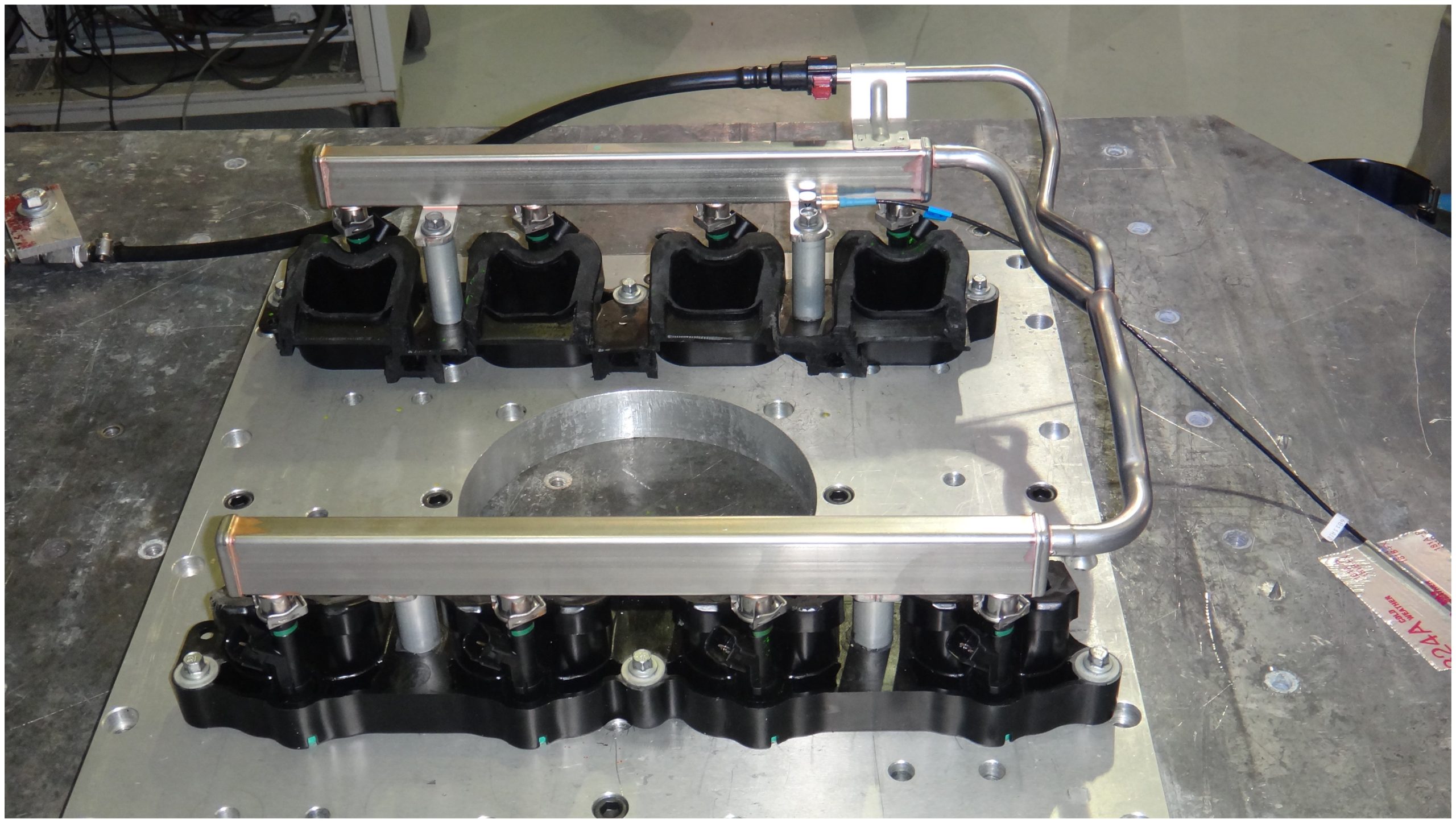
Generally, the control accelerometer should be on the fixture close to the attachment point, and the attachment of the component should reflect the end-use configuration, if possible. The system puts energy into the shaker, which transfers to the fixture, and then the component, so this general rule helps ensure that the DUT experiences the desired vibration levels.
That said, there are exceptions. A test standard may indicate where to mount the control accelerometer. In this case, the engineer should heed the standard’s advice while keeping in mind the safety of their specific test setup. If the engineer has generated a test profile from field data, they should mount the sensor in the same location from which they recorded the data but orient it in the axis of the shaker excitation.
As mentioned previously, engineers should avoid vibration nodes or locations with little to no vibration. Additionally, mounting the control sensor on the head of the shaker won’t consider the fixture’s behavior and is not recommended.
Multi-point Control
With more complex single-shaker test systems, engineers may likely use multiple control accelerometers, selecting an average/weighted average or maximum value. If the DUT is fixed at more than one point, and the behavior at the fixing points differs, then the engineer may choose multi-point control. In other test scenarios, an oversized fixture, such as a slip plate, may require control at multiple points. Large slip plates or armatures may resonate during testing, particularly at the ends of free systems.
The following clip from our Aerospace and Defense tech talk video discusses the multi-point control strategy in more detail.
Multi-point control is a more advanced test setup and requires a separate discussion in terms of approach.
Control Strategy and Post Analysis
Engineers should plan their approach to measurement before testing whether for single or multi-point control. Once they’ve determined a control location, they should conduct a preliminary test to evaluate the response and adjust if necessary. Engineers should document any anomalies during these tests that could affect the results. They should approach the data considering the control accelerometer’s placement, recognizing that localized readings may not reflect the entire system’s behavior.

