The ObserVIEW Random Test Generation software can create an accelerated random test profile from multiple channels, files, or analysis ranges in versions 2025 and newer. The output is a random power spectral density (PSD) that is the damage equivalent to the product’s estimated lifetime use. You can export the PSD to run the test in the VibrationVIEW control software.
QUESTION
How do I create an FDS-correlated random test using the Random Test Generation software?
ANSWER
- Open a time-history waveform recorded file
To add analysis ranges to the time waveform or add an additional file to the project, navigate to the Analysis Ranges pane and select Add Analysis Range or Add File.
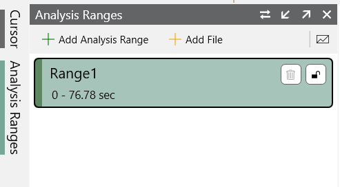
Analysis Ranges pane.
NOTE: The recorded files should represent the vibration a product experiences in a lifetime. The recordings do not have to be an exact replica of a lifetime of damage, but they should be as close as possible.
- Edit the time waveforms as needed, which may include filtering or resampling
- On the main Home ribbon, select the Random Test Generation button; a new Test tab will appear in the main graph
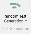
Random Test Generation button.
Vibration Groups
- Create the Vibration Groups; these groups allow you to organize data ranges/files into different vibration environments—e.g., highway, gravel, and city environments, x, y, and z axes, etc.
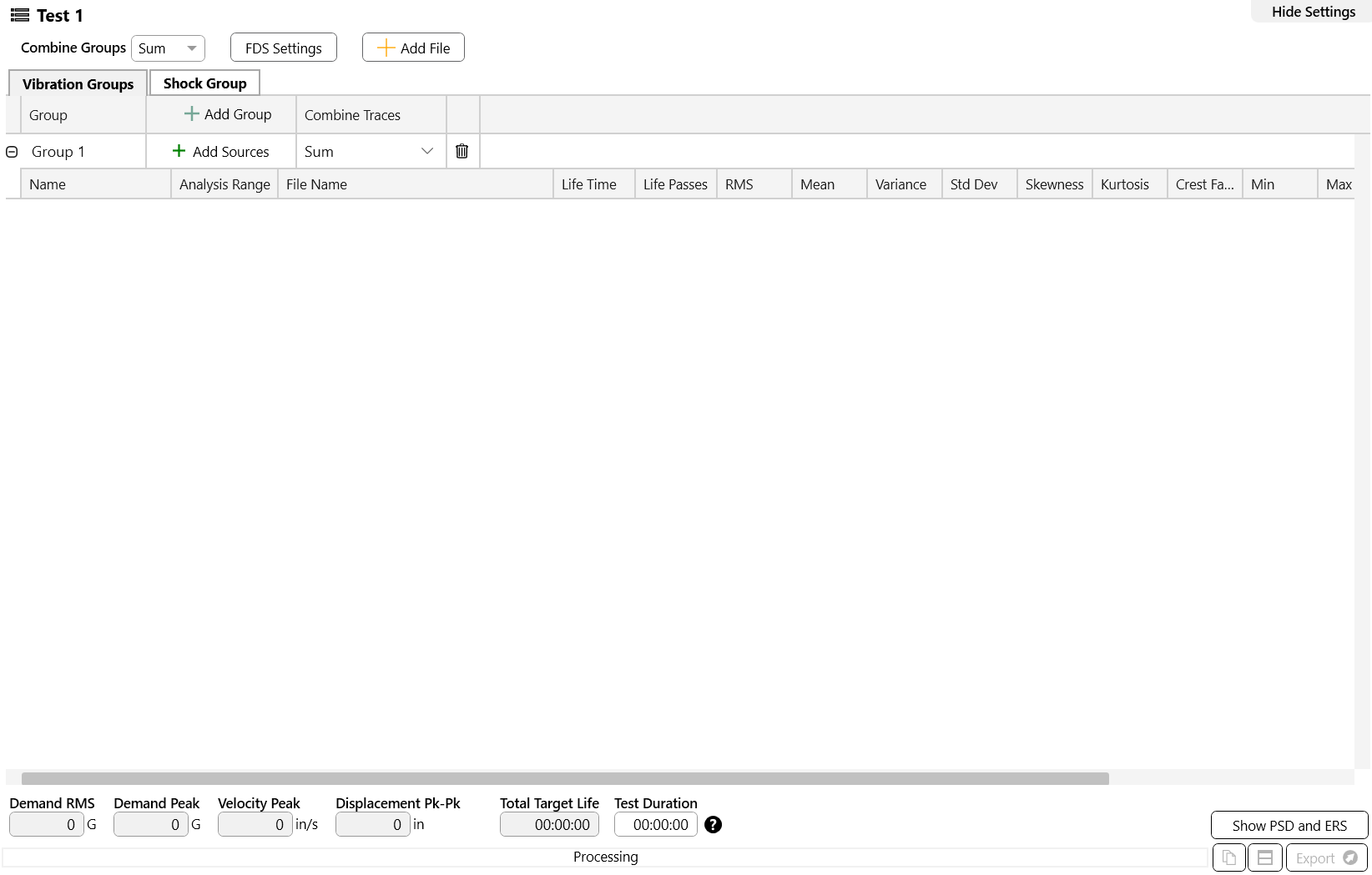
Vibration Groups settings.
-
- Select the Add Sources button to add/remove sources to/from each group
- Use the Combine Traces drop-down list to select an option for combining the group’s damage profiles (envelope or sum)
- Define the percent of the total target life spent at each source in the Life Time column and the number of life passes in the Life Passes column; the software will calculate the statistics for each trace accordingly
- The target life is the time or number of cycles the control system should run the waveform to represent one lifetime of damage; for example, it can be the length of a product warranty or the time the product should survive when exposed to the waveform
- The graph can display the combined damage, random vibration test PSD, extreme response spectrum, or all three options
- If you have multiple Vibration Groups, use the Combine Groups drop-down list to select an option for combining the vibration groups’ damage profiles (envelope or sum)
Fatigue Damage Settings
- Navigate to the Properties pane and confirm the fatigue damage settings
- Under the Fatigue Damage Options, enter the appropriate m and Q values for the device under test
- If adding Kurtosion® Time Compression, enter a kurtosis and transition frequency value
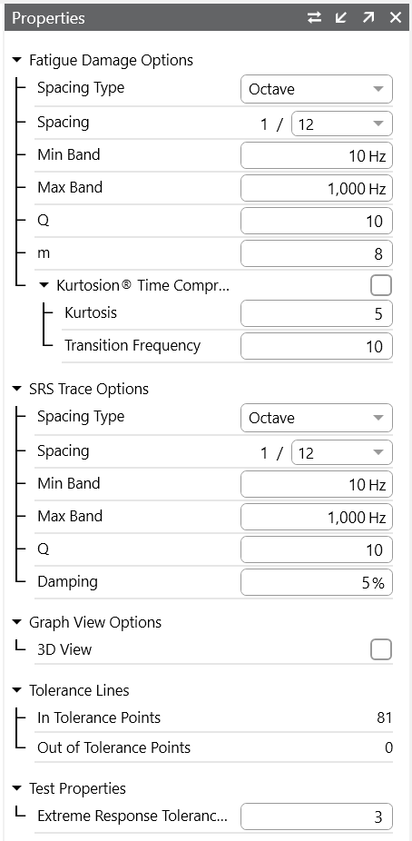
Fatigue Damage options.
NOTE: Reducing the frequency range to the bins of interest or increasing the octave spacing will save calculation time.
Kurtosis
An engineer may want to increase the kurtosis of the random PSD to reflect the peaks of the imported time-history file(s), particularly when the waveform’s kurtosis is high (k>3). With Kurtosion, it is possible to introduce kurtosis and vary the transition frequency to create peaks that represent the original files. The FDS software will automatically adjust for the added kurtosis to ensure that the generated profile is the damage equivalent of the input waveform(s). You can reference the Demand Peak value to validate your kurtosis setting.
Test Acceleration & Validation
- Enter the Test Duration
The software can accelerate the test profile (test duration), but an accelerated test is not the same as a test run for the full amount of time. The less the test is accelerated, the more accurately it represents real-world data. Additionally, test acceleration is only as accurate as the m value for the product. The more the test is accelerated, the more important the m accuracy becomes. At a minimum, the instantaneous stress limit of the product cannot be exceeded.
Shock Group
- The Shock Group is used for extreme response validation. If your recording has shock data, you can create a shock group from one or multiple files. The software will generate a shock response spectrum that can be compared to the ERS tolerance. If your recording does not have shock data, the software will generate a test ERS from the vibration data.
ERS Tolerance
- The ERS Tolerance provides a reference trace to confirm that the acceleration factor is appropriate; the default is 3x the test ERS/SRS. You can compare the demand ERS to the accelerated test profile to confirm the test duration. The test ERS/SRS should not exceed the tolerance ERS.
Export Profile
- The Demand RMS, Demand Peak, Velocity Peak, and Displacement Peak adjust to the user settings; if your shaker system can meet these values, you can copy the profile to the clipboard, export it to a CSV, or export it to VibrationVIEW for testing
The random PSD generated is the damage equivalent to the lifetime of the product based on the imported files, m and Q values, target life, test duration, and kurtosis.