Abstract
GMW14201 defines a rearview mirror performance test approved by General Motors Corporation. It is a rotational vibration measurement test for inside and outside automotive rearview mirrors and measures the mirror’s rotational response when subjected to vertical input vibration.
Question
How do I perform a test that meets GMW14201 with Vibration Research (VR) hardware and software?
Answer
Equipment
VR recommends the following equipment for conducting the GMW14201 test:
- GMW14201 specification
- VR9700 or VR10500 vibration controller -or-
- ObserVR1000 keyed as a controller
- RandomVIEW software test module
- RecorderVIEW waveform recording option
- ObserVIEW 2023.1 or newer -or-
- MATLAB 7(r14) or newer and GMW14201 MATLAB script
- Four (4) lightweight, single axis 50 to 100 mV/g accelerometers with low transverse sensitivity
- Shaker with fixturing capable of running the specification
Test Setup
The mirror assembly is mounted to a rigid fixture on a shaker head. The procedure instructs the engineer to mount three accelerometers on the mirror’s reflective surface in a triangle formation. They should measure and document the distance in meters (m) between each lens accelerometer. The fourth accelerometer is mounted to the base of the fixture.
Figure 1 displays an example shaker setup, including the location of the lens accelerometers.
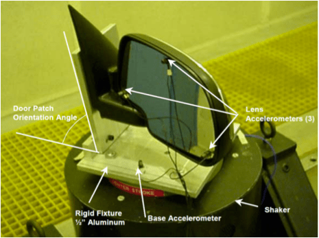
Figure 1. GMW14201 shaker setup for an external rearview mirror; copyright of General Motors Corporation.
Figure 2 is an example setup of an inside rearview mirror test performed at VR headquarters. Note that triaxial accelerometers were used on the lens, and the y-axis (lateral) recordings were utilized in the analysis.
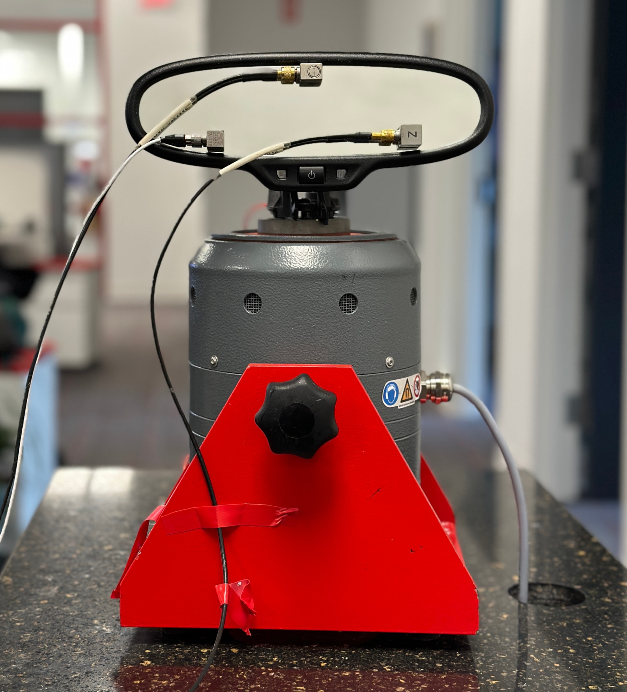
Figure 2. GMW14201 shaker setup for an internal rearview mirror.
Running the Test
The procedure calls for a random test profile with a different overall root-mean-square (RMS) level for outside and inside mirrors. It does not provide a breakpoint table but includes example input spectra in units m/s2 RMS. Several parameters for the acquisition system are also defined, including frequency bandwidth and resolution.
To build a test profile, VR uploaded a field recording of an internal mirror to the VibrationVIEW software and scaled the RMS level to meet the standard.
The random test profile shakes the mirror vertically. As the test runs, VibrationVIEW uses RecorderVIEW to record the values of the input and response accelerometers at a high sample rate.
Post-process
After running the test, the procedure requires that the engineer computes the dynamic rotation of the mirror (the mirror’s total angular acceleration spectrum). Due to the accelerometer arrangement, the difference in acceleration between two accelerometers divided by the distance between them determines their angular acceleration (rad/s2).
Figure 3 is a 2D representation of the triangular array in Figure 1. X1, X2, and X3 represent the readings of the three physical accelerometers in Figure 1. X4 is a virtual, estimated accelerometer. A13 and A24 in Figure 2 denote the angular acceleration calculated between points 1 and 3 and 2 and 4, respectively. A13 represents the yaw of the mirror, and A24 represents its pitch.
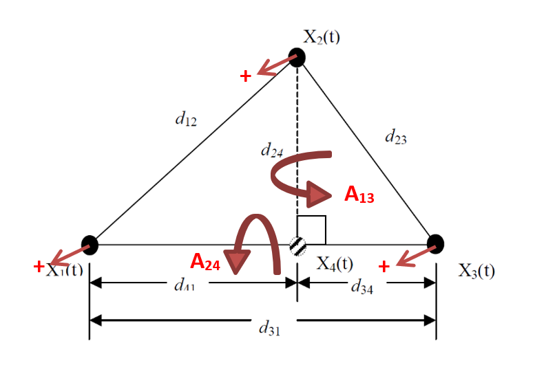
Figure 3. GMW14201 mirror rotation setup schematic; copyright of General Motors Corporation.
First, the engineer needs to calculate the distance between X2 and X4 (A24) using the law of cosines.
(1) 
Equation 1
(2) 
Equation 2
Then, they estimate the acceleration at X4 by interpolating in the time domain between point 1 and point 3.
(3) 
Equation 3
Calculating Total Angular Acceleration
After estimating the acceleration at X4, the engineer can begin calculating the total angular acceleration. Engineers can use the Math Traces feature in the ObserVIEW software or a custom MATLAB script to do so.
Math Traces
In the ObserVIEW software, VR imported its test recording to calculate the total angular acceleration using Math Traces.
First, the procedure instructs to calculate the time domain angular acceleration (rad/s2) between points 1 and 3 and 2 and 4. VR calculated the angular acceleration between points 1 and 3 with the following expression:
(“X1-FA” – “X3-FA”) / 0.115
X1-FA and X3-FA are the acceleration signals for point 1 and 3, and 0.115m is the distance between them.
As point 4 is an estimate, VR calculated the angular acceleration between points 2 and 4 using the estimation calculation (Equation 3) in place of point 4.
(“X2-FA” – (“X1-FA” + (0.058 / 0.115) * (“X3-FA” – “X1-FA”))) / 0.039
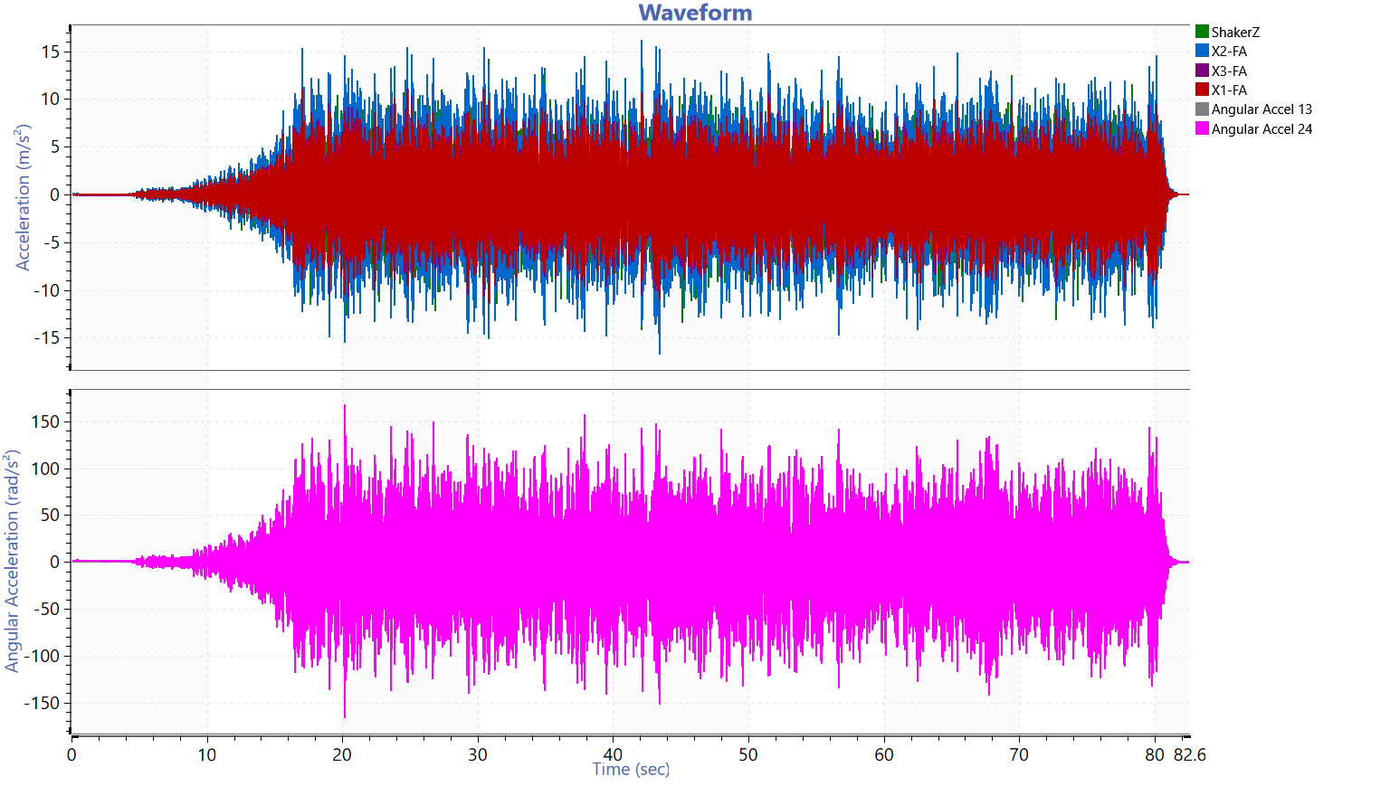
Time waveform of the three lens sensors and the angular acceleration calculated for points 1 and 3 and points 2 and 4.
Per the procedure, VR calculated the auto-power spectra of the angular accelerations using the provided processing parameters by generating a power spectral density graph from the time-domain data. VR combined the spectra using the following expression.
sqrt((sqrt(“Angular Accel 13″^2 + “Angular Accel 24″^2)) / ((2 * PI * freq())^4)*v1.df())
The expression (sqrt(“Angular Accel 13″^2 + “Angular Accel 24″^2)) combined the angular accelerations.
Double integration (2 * PI * freq())^4) was necessary to achieve the dynamic angle of rotation spectrum of the mirror. Multiplying the expression by the bin width (v1.df()) and taking the square root of expression converted the value from rad2/Hz to radians.
Figure 5 is the acceleration profile for the shaker, and Figure 6 is the dynamic angle of the mirror, and Figure 7 is the transmissibility for X1, X2, and X3 and the shaker. The transmissibility identifies the first resonant frequency, which the procedure also requires.
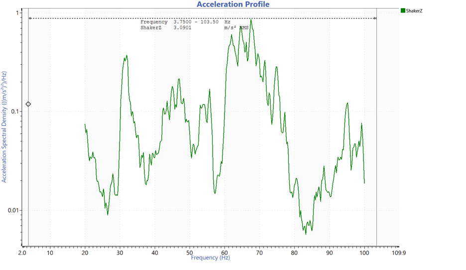
Figure 5. Acceleration spectral density of the dynamic rotation with an overall level of 3.0901 m/s2 RMS.
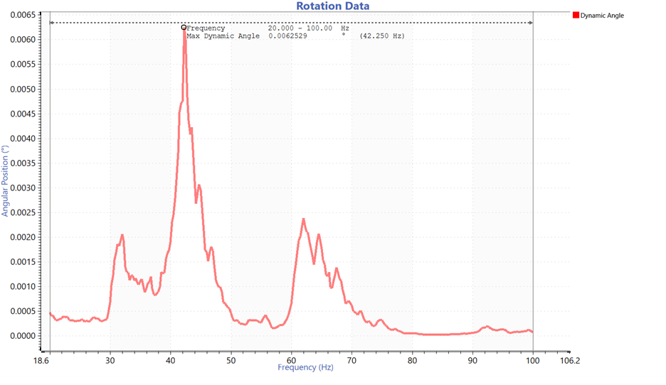
Figure 6. Angular position of the mirror with a maximum dynamic angle of 0.00625 degrees.
Figure 7. Transmissibility of the three lens sensors and the shaker.
MATLAB Comparison
The MATLAB script outputs a series of graphs. One is transmissibility vs. frequency, and the other is rotation vs. frequency. VR ran the data through the MATLAB script to compare the processes. The transmissibility and rotation data are comparable.
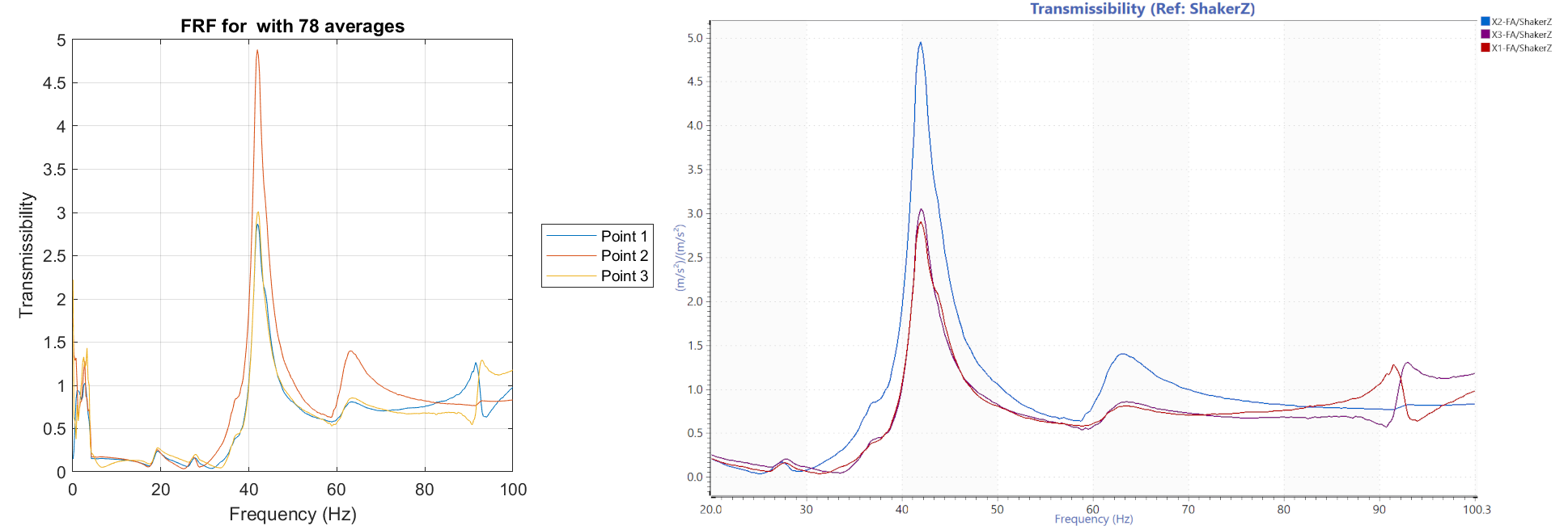
Figure 8. Comparison of transmissibility functions.
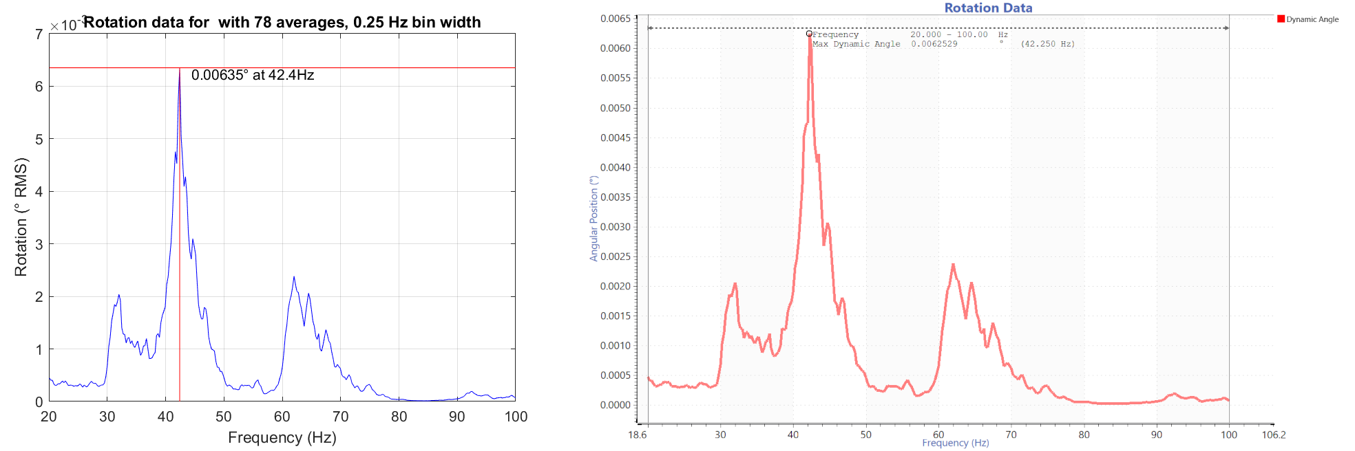
Figure 9. Comparison of rotation data.
Visual Validation
VR also performed a visual calculation of the angle to confirm the math. They pointed a laser at the mirror, which reflected onto the wall. They measured the distance from the mirror to the wall, and then ran a sine dwell test at resonance.
As the test was running, they marked the movement of the laser from its center point. When the test finished, they measured the laser’s peak movement from the center.
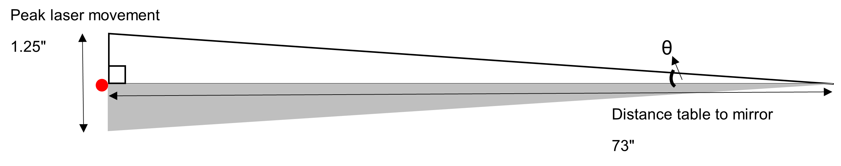
VR calculated the mirror angle (θ):
(4) 
When VR used math traces to calculate the angle for the same sine dwell test, the numbers were within a reasonable factor. Engineers can use this visual method to confirm their GMW14201 results.
Learn More
If you are interested in running the GMW14201 specification with the recommended tools above, please contact Vibration Research Corporation’s sales department at vrsales@vibrationresearch.com.
Last updated: April 12, 2023.