Abstract
A customer wanted to use the VR9500 remote I/O and VibrationVIEW to initialize a start-up sequence for their hydraulic power supply. They also wanted to have an input condition satisfied before the user could begin to “Run” a test profile.
Question
- How should the remote inputs and outputs be configured?
- The customer was concerned the output did not have sufficient voltage to drive his solid state relay (SSR) after checking the contact side for continuity with ohm-meter.
Answer
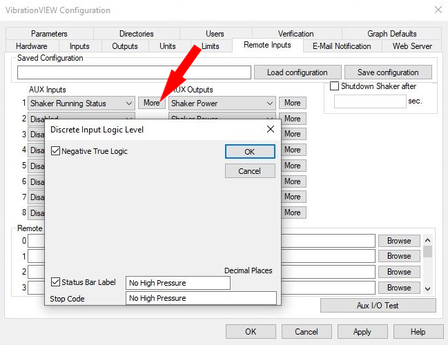
CONFIGURING REMOTE I/O
The customer was using Grayhill SSR and needed output voltage to be 4-5VDC. We recommended:
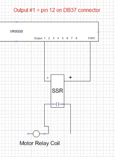
- Connect 5VDC from VR9500 to Pos(+) side of Grayhill SSR.
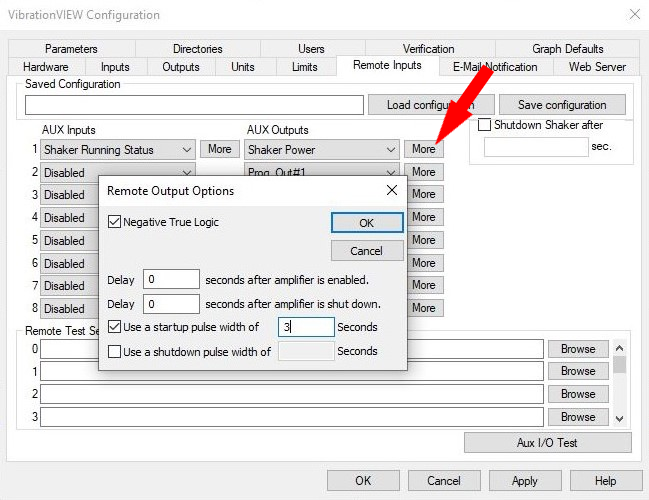
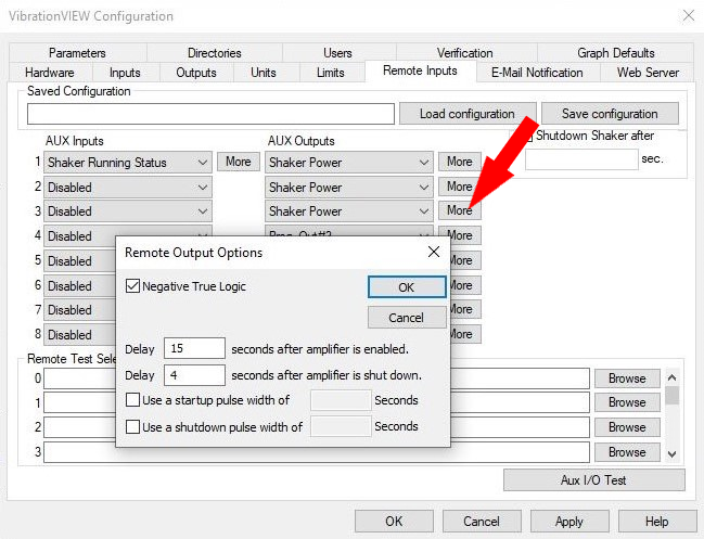
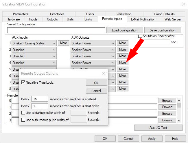
- Connect a VR9500 Output to Neg(-) side of Grayhill SSR. (note – when output is “off” there is 5VDC present, so must use Negative True Logic in software configuration).
- NOTE: The 5VDC terminal on VR9500 is limited to 120mA. Use an external 5VDC power supply if requirements exceed 120mA.
- STEP 1 | Output #1 = pin 12 on DB37 connection
- Start HPS Motor.
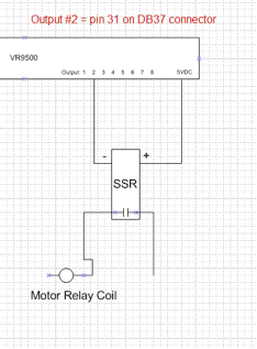
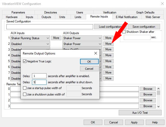
- STEP 2 | Output #2 = pin 31 on DB37 connector
- Latch HPS motor “on” to prevent auto-restart if safety tripped.
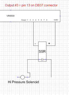
- STEP 3 | Output #3 = pin 13 on DB37 connector
- Open the high-pressure solenoid. Wait 15 seconds for the soft start to complete.
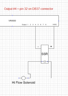
- STEP 4 | Output #4 = pin 32 on DB37 connector
- Open high flow solenoid.
CHECKING CONTACT SIDE OF SSRs
The customer checked the voltage across VR9500 “5VDC terminal and Output terminal” with and without SSR connected. They measured approx 4.8VDC without SSR connected and approx 4.2VDC with SSR connected. The customer felt the voltage drop was too great.
The customer then connected ohm-meter across the contact side of SSR and applied an input voltage. The customer was concerned because SSR LED flashes on but contacts did not close completely and felt the VR power supply was not sufficient because of voltage drop. Vibration Research informed the customer that the voltage drop when a load is connected is normal. Checking SSR’s contact side requires that a load be applied (typically min 0.1A). Using an ohm-meter does not provide sufficient load.