Article Overview
- Overview of the four-poster rig
- Setup for buzz, squeak, and rattle (BSR) testing
- Developing a test profile
- Method of four-poster shaker control
For automotive reliability testing, outdoor testing is ideal but not always practical. In response, the industry has developed indoor test setups to replicate outdoor tracks. These tests must replicate the operational environment to be effective. However, they offer the benefit of repeatability and test acceleration.
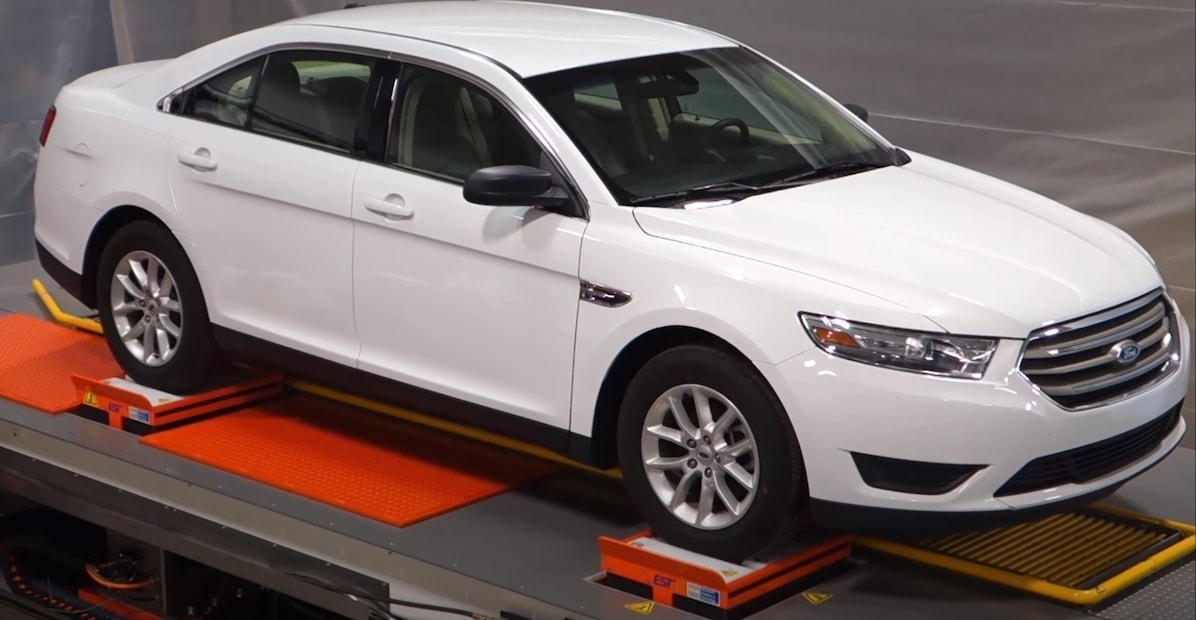
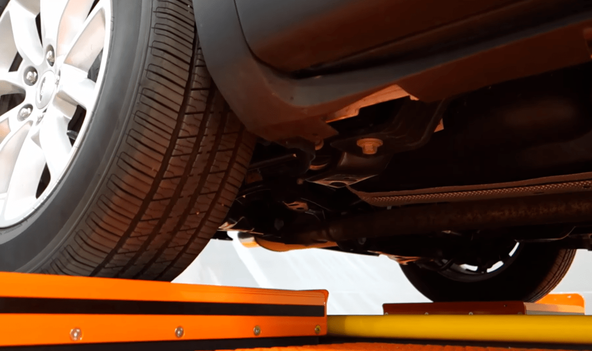
The four-poster rig is an accepted method of road profile simulation. Typically, it is a hydraulic system where the four tires of an unrestrained automobile sit on separate pedestals. Engineers use the setup for durability testing, NVH testing, frequency response identification, and more. Road conditions impact the automobile’s suspension and frame most, so the 4-poster often functions to validate these specific components.

Four-poster for BSR Testing
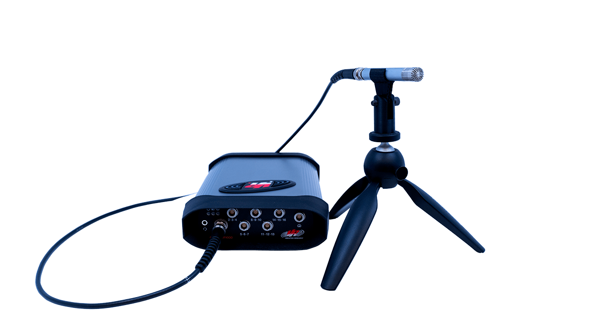
 Components excited by road conditions generate some form of noise, and audible disturbances should be minimal for passenger comfort. Buzz, squeak, and rattle (BSR) testing outputs a vibration signal to excite a response in the automobile, which is then detected with acoustic analysis.
Engineers use this test type to evaluate vehicle components based on the noise they generate while in use. The test results depend on a human interpretation of the noise or sound quality metrics such as loudness, kurtosis, and roughness.
Engineers often use a four-poster rig for BSR testing, as the test setup reflects the operational environment. They may perform the test in a 4-poster-chamber for more specialized temperature or noise control.
Developing a Test Profile
To perform a four-poster vibration test, the engineer first creates a test profile to control the system. The vibration controller uses the profile to send signals to the hydraulic system to excite the device under test (DUT) accordingly.
A test profile for a 4-poster rig must reflect the operational environment as closely as possible. Ideally, the engineer takes recordings from an outdoor test to develop the indoor test profile. However, engineers may use historical data or a test standard when field recording is not possible.
After the engineer has developed the test profile, they may decide to accelerate it. Automobiles withstand years of shock and vibration. Accelerated test profiles can help identify potential fatigue and determine the lifespan of a component or full vehicle.
Controlling a 4-poster Setup
 A four-poster configuration excites four shakers along the same axis (usually the z-axis). The engineer plays back the recorded data files for each wheel. Then, they playback the recordings simultaneously as if the vehicle was in motion.
The vibration controller forms the drive signal by comparing the control acceleration from the shaker table/DUT with the demand reference. The control algorithms minimize the difference between the control and demand signals by adjusting the shape and amplitude of the drive signal.
This referencing of control and demand forms what is called a control loop. When the controller(s) sends independent drive signals to multiple shakers, the system performs multi-loop control. Multi-loop control is common when more than one shaker is controlling a test item on a single axis.
Example Set-up
A multi-loop test in VibrationVIEW requires a VR10500 with multiple loops enabled. The primary VR10500 controller must drive all outputs, but the system can have stacked controllers for more than 16 inputs (up to 512).
The Sine, Random, Shock, and FDR test modes can run 2, 3, or 4 output drive loops simultaneously but offer different options/capabilities for control. Multi-loop Sine is available with the VR10500 only.
Four-poster System for Automotive Testing
The four-poster rig is a powerful method for replicating real-world road conditions in the lab. By synchronizing four independent hydraulic actuators with accurate field-derived profiles, engineers can subject vehicles to repeatable, accelerated stress and BSR noise tests. This controlled setup replicates field environments, helping engineers identify fatigue-prone components within a flexible and repeatable framework.
Automotive manufacturers take vehicles for test drives on outdoor tracks to replicate the end-use. However, indoor testing with a 4-poster rig is comparable in accuracy, so long as the test profile reflects the operational environment. A multi-control loop system ensures that the drive signal meets the demand, and field recording helps to develop more accurate profiles.
