Run a dwell test at specified resonant frequency until failure
After determining transmissibility peaks, run a dwell test at resonant frequencies for a specified time duration or number of sine wave cycles. Sine resonance track & dwell (SRTD) excites the known resonance until failure or sufficient time has passed without failure. SRTD is a Sine software add-on.
Sine resonance control tracks a resonant frequency by adjusting the drive frequency to hold constant the relative phase between two input channels. The SRTD software add-on simplifies sine dwell tests with options for automatic selection and control. VibrationVIEW can automatically:
Select resonant frequencies
Annotate resonances
Process transmissibility and phase plots
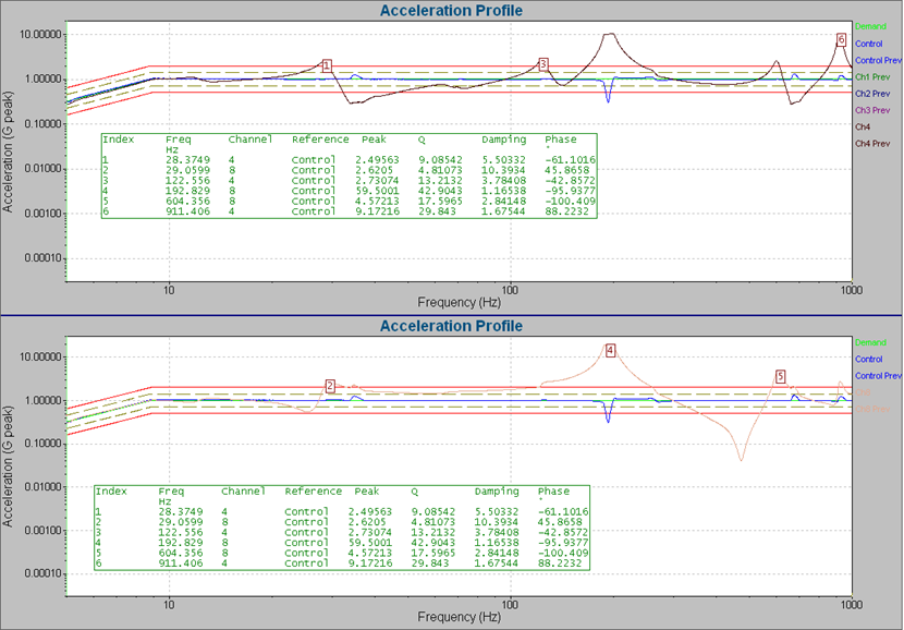
The software annotates the defined resonance peaks with the Q value, phase, and damping. You can document the resonances in an automatically generated report.
Dominant Single-frequency Vibration in Real-world Systems
Turbines and pumps operating at a fixed RPM
Electric motors
Propeller blade-passing frequency
HVAC compressors
Gear-mesh frequencies
Medical centrifuges
Rotating fans in electronics
SRTD Controls
Manually change SRTD settings during a test and receive feedback on current test settings in the SRTD Controls dialog box.
The time-based SRTD graphs display long-term changes in the resonance frequency due to fatigue or product temperature. The phase-based SRTD graphs have a custom layout.
What is Sine Resonance Track Dwell?
An SRTD test brings a product to failure by exciting a known resonance. The vibration controller runs a single sine tone at the product’s resonant frequencies rather than sweeping through the frequency range.
During a sine dwell, the controller can automatically track the resonance frequency so that the output remains on the resonance even if fatigue damage shifts the resonance frequency.
In VibrationVIEW, track high-Q or sharp resonances with advanced phase tracking controls that allow you to dial in on resonances and maintain peak amplitude by way of phase versus transmissibility.
Automatic Peak Tracking
Peak tracking in VibrationVIEW automatically shifts resonances by finding and maintaining the peak transmissibility between two channels.
This powerful feature minimizes the need for precise detection during the sine sweep so the test can sweep faster. Most importantly, it maintains peak transmissibility throughout the tracked dwell portion of the test.
Adaptive Feedback
A sine sweep test may display oscillations in the presence of high-Q resonances. Engineers can address the oscillations in several ways, such as adjusting the response time or tracking filters. However, these parameters are fixed in some situations and cannot be adjusted. In such instances, they can use the Adaptive Feedback option.
Adaptive feedback allows for tighter control while limiting problems in a resonance. A majority of tests only require one set of settings. As the test sweeps through the resonance and begins losing control, the software automatically adjusts the response time and slew rate to more appropriate settings.
Part number 9105
VR9105
Fundamentals of VibrationVIEW - Sine Resonance Track & Dwell plus High Q Sine Testing
Easy Test Entry in Sine
SRTD is an add-on to the Sine software. In Sine, automatically detect resonances using a swept and/or fixed-frequency sine wave test with control of acceleration, velocity, or displacement.
Enter frequency or amplitude breakpoints in an easy-to-read, tabular format. VibrationVIEW supports 1,024 breakpoints in Sine, suitable for virtually any test specification.
Control constant or ramped acceleration, velocity, or displacement.
Automatically calculate the frequency of the intersection between any constant acceleration, velocity, or displacement.
Input Configuration
Configure up to 512 input channels with multi-channel averaging or multi-channel extremal control. The standard frequency range is DC-4,990Hz, which can be extended up to 50,000Hz with the VR9103 High-Frequency option.
VibrationVIEW supports multiple control input channels (multi-channel extremal) when using the highest, lowest, or average accelerometer readings for test control. Input channels can have individual tracking filters to remove harmonics and out-of-band noise from measurements.
Sine Sweep
Run sequences of fixed-frequency tones of a specified acceleration, velocity, or displacement. Test duration options include the length of time, the number of sine wave cycles, and the number of sweeps.
Additional Features
Specify linear or logarithmic sweeps
Change the sweep type while the test is running
Easily repeat tone sequences with the looping function
Set individual sweep rates and tolerances by segment
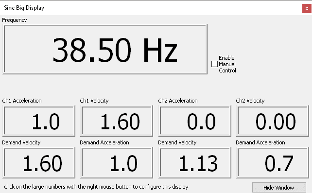
A configurable large numeric readout displays the current test frequency and channel amplitudes. Use the manual control to manually control the sweep direction, sweep rate, and scale the amplitude with your mouse cursor.
Configurable Safety Limits
The controller can be configured to abort if the controlled acceleration goes above or below the desired level by an operator-configured number of dB. Abort limits can also be enabled for individual monitoring channels. Drive limits can be configured to protect from overdriving your shaker in case of failed accelerometers.
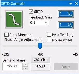 Manually change SRTD settings during a test and receive feedback on current test settings in the SRTD Controls dialog box.