Once you’ve decided that the accelerometer is a suitable sensor selection for your vibration test, there are several considerations for test setup, including sensitivity and cable length.
We recently received a few customer questions regarding accelerometer selection and setup. We’ve published the following questions & answers so other customers can review these accelerometer considerations for vibration testing.
QUESTION 1
How do I select the optimal accelerometer and sensitivity depending on the required test conditions? For example, most tests are 3G peak sine dwell and a 50G, 11mS classical shock pulse. What accelerometer sensitivity would you recommend for these test profiles?
Answer
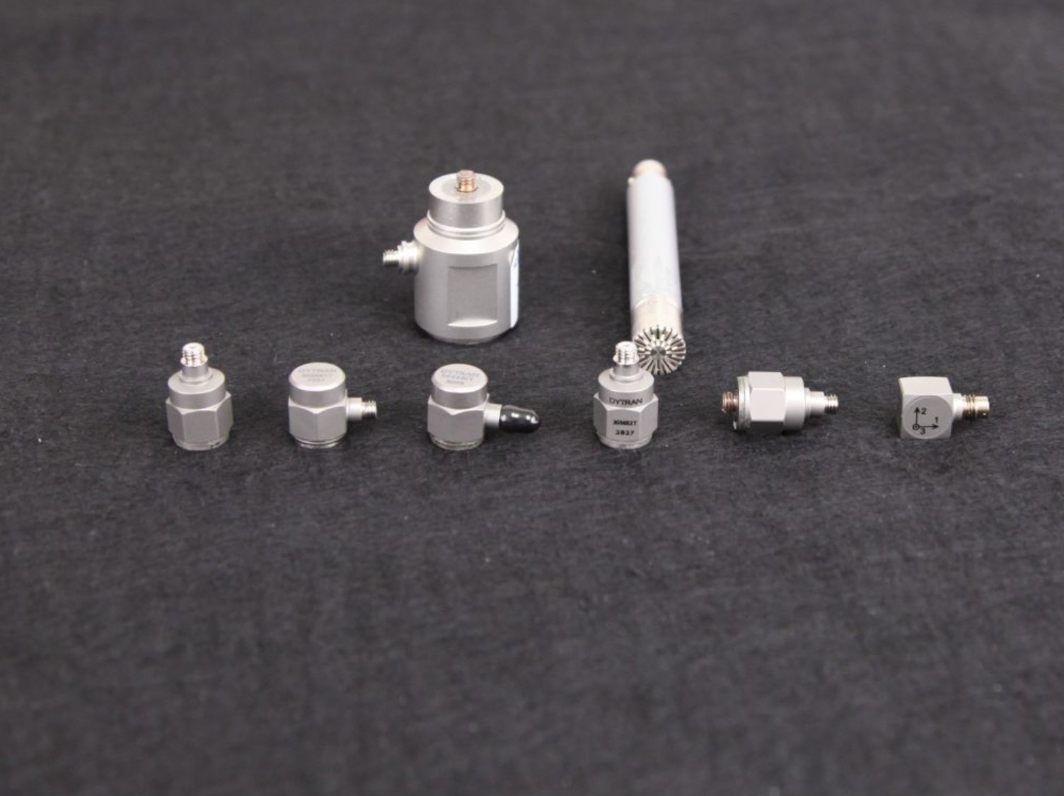 The current sensors market features many accelerometer types. The accelerometers’ specifications vary based on maximum acceleration, frequency range, test environment, etc.
In terms of an “optimal” accelerometer, we recommend using an integrated electronic piezoelectric (IEPE) accelerometer with transducer electronic data sheets (TEDS) for most test environments. An IEPE accelerometer powered by a constant current provides a clean signal and removes many of the noise sources that are common with other types of accelerometers. A TEDS chip contains the sensor’s sensitivity and other details, which reduces the possibility of operator error.
Accelerometer Sensitivity
Entering the incorrect accelerometer sensitivity can cause significant damage to the shaker. The TEDS chip holds the critical information required for a test (calibration date, manufacturer, sensitivity, output range, model number, etc.). TEDS ensures that the control system has the correct sensitivity of a connected accelerometer.
The most common sensitivities for accelerometers in vibration testing applications are 100mV/G and 10mV/G. Common IEPE accelerometers can output a ±5V excitation signal. The range of a 100mV/G accelerometer with a ±5V output is 50Gpk (5Vpk / 100mV = 50Gpk) and 500Gpk (5Vpk / 10mV = 500Gpk) for a 10mV/G accelerometer. These accelerometers can generate a signal greater than ±5V; beyond that point, the response is no longer linear, and the overall measurement uncertainty increases significantly.
For the test profiles in Question 1, a typical IEPE and TEDS 100 mV/G sensor would be an ideal accelerometer for the low amplitude (3Gpk) sine dwell test, but would not be the best choice for the 50Gpk shock test. A 10mV/G accelerometer would be much more fitting. Most vibration testing laboratories have 10mV/G and 100mV/G accelerometers on hand for different applications.
QUESTION 2
Is there a rule of thumb concerning the maximum accelerometer cable length?
Answer
 Simply put: the shorter, the better. The cables in a vibration testing system are one of the most easily damaged components and are typical sources of noise problems.
Cables get strewn across the floor, scraped, and kinked, and the shielding breaks down. As the shielding breaks down, the environment’s radiant electrical noise is induced into the cable and measured by the controller. This noise is environmental; therefore, the controller cannot control it. This scenario applies to the drive output cable between the controller and amplifier and the accelerometer cables between the accelerometers and the controller. Eventually, the ground/shield bond established by the cable will fail, and any generated or measured signal will have no real reference. This failure can damage other components in the system.
Environmental noise is one reason Vibration Research uses a 1000 Base-T Ethernet connection between the controller and PC. It allows engineers to install the controller close to the amplifier and shaker while the operator station can be in a control room up to 300ft (100m) away. The shorter cables (drive and accelerometer) are more easily maintained and cost-effective, and reduce confusion when determining which accelerometer is connected to a particular channel.
Max Cable Length
The maximum cable length depends on the type of accelerometer and cable. For example, the distance between a charge mode accelerometer and the charge barrel/amplifier must be short. These accelerometers output very low voltage levels, and any noise that the cable absorbs from the environment can cause variation in the signal.
The wire that carries the voltage supplying power to an IEPE accelerometer also carries the signal. The signal has much more power and is less subject to variation. As the cable length increases, the inherent impedance and capacitance changes. Depending on the cable type and the output of the IEPE power supply (2mA vs. 5mA), the maximum length can be up to several hundred feet for a well-insulated and low-capacitance straight cable. Joining multiple cables, running cables near high-voltage wires, and other factors will affect the signal and may cause issues.
Additional Considerations
Accelerometer Calibration
Calibration accurately determines an accelerometer’s sensitivity at various frequencies of interest. A calibration schedule helps labs detect incorrect sensor sensitivity and discover sensor defects to ensure confidence in their results. Vibration Research’s Accelerometer Calibration software performs an automatic and accurate calibration and verification of IEPE accelerometers and charge-mode piezoelectric accelerometers/transducers.
Why Calibrate?
- Early detection of incorrect sensor sensitivity
- Discover sensor defects
- Confidence in your test results
Accelerometer Mounting
When conducting a vibration test, it is important to consider the various methods of accelerometer mounting. Some methods are more reliable, but the test requirements may take precedence. In the following article, we discuss three of the most common accelerometer mounting methods.
Test Setup Checklist
A vibration test system has many components and requires diligence with each new test setup. Costly mistakes can damage your shaker system and waste time. Nothing is worse than scheduling a test but needing to wait because of setup problems. What’s worse is reporting these delays to your customer and rescheduling their test for weeks down the road. Don’t let this happen to you! Download Vibration Research’s test setup checklist, which includes accelerometer and cabling considerations.