To run a conventional vibration test on a shaker system, engineers mount larger structures at one or several fixed attachment points to the shaker. However, the hard mounting of the structure can result in large base reaction forces at its resonances. The conformity of motion at the attachment point(s) is not present in the actual environment, and the mechanical impedence of the shaker can result in over-testing. To prevent this behavior, engineers may set limits with force-limited vibration testing (FLVT).
FLVT prevents over-testing due to these large base reaction forces or other responses at the structure’s fixed-base resonant frequencies. It is used to override the Demand:Control loop to limit or notch the acceleration at specific frequency ranges where forces are amplified.
Force limiting is a standard technique in aerospace testing and applicable to many industries. Large test articles, such as vehicle batteries, rockets, missiles, and other structures, could benefit from this technique to prevent over-testing compared to their real-world environments.
Article Overview
- Overview of time-domain force limiting
- Configuring virtual channels for Sine and Random tests
- Discussion of overturning moments
- Introduction to processed data calculations
- Example virtual channels application
- FAQs
Methods
The aerospace industry has established requirements for FLVT, such as those outlined in NASA-HDBK-7004C. These accepted techniques help protect the test article while replicating vibration levels representative of real-world launch environments.
Common Specifications and Standards
- ISO 23670:2021
- MSFC-STD-3676B
- NASA-HDBK-7004A
- SpaceX Rideshare Payload User’s Guide
- SMC-S-016
Time-domain Force Limiting
Time-domain force limiting is an FLVT technique that utilizes virtual channels. Virtual channels perform linear math operations on raw time signals to combine physical input channel data. Calculations in time, as opposed to frequency, account for the phase of a waveform.
Engineers can use time-domain force limiting in combination with processed data calculations to implement effective notching, protect the test article, and generate force inputs that represent the launch environment.
Virtual Channels in VibrationVIEW
Virtual channels are the result of a user-defined expression that combines input channels. They perform linear math in the time domain and can reference channels across hardware units.
Engineers can reference virtual channels when configuring notches/aborts in a Sine or Random test profile. They can use virtual channels in the same way as a response channel from a physical sensor. VibrationVIEW identifies virtual channels as inputs, which engineers can use as a part of their control solution.
VibrationVIEW’s virtual channels include computational abilities specifically for force-limited vibration testing applications, including the sum of load cells (summed force) and overturning moments.
Features
- Calculate values live and apply limits in real-time
- Define expressions across hardware units
- Define up to 16 virtual channels
- Add virtual channel definition to reports
- View virtual channels in any graph overlaid with individual channel data
- Save and load virtual channel configurations
Random Vibration Testing
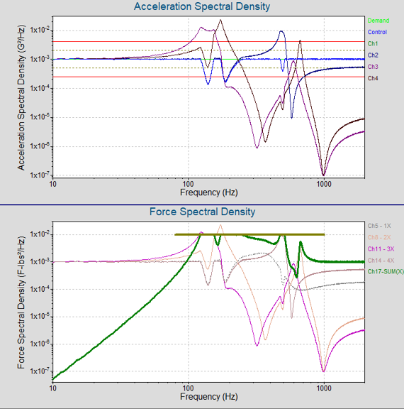
In the Random test mode, a range of analysis tools can be used to understand the data from the virtual channel, including time-domain analysis tools, statistical time-history data, FFT, PSD, and transmissibility. Engineers can apply individual boost, notch, and abort tables to each virtual channel, allowing for effective force-limited vibration testing.
The individual channels’ PSD, composite virtual channel, notch table, and ± abort lines can be added to a graph for simple, effective analysis and validation against the defined notch and abort tables.
Sine Vibration Testing
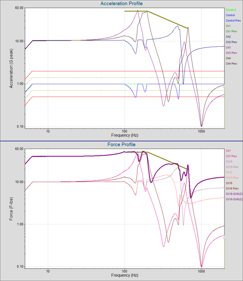
In Sine, VibrationVIEW passes the virtual channel’s raw time data through tracking filters defined in the test profile. The output can be plotted on any sine analysis graph.
Engineers can assign notch and abort limits to each channel. They can adjust the tracking filter bandwidth, controller response time, and other tuning parameters to optimize settings for different sweep rates and test profiles.
These features enable excellent sine control with minimal overshoot in virtual channel measurements. Combining fractional and maximum bandwidth tracking filters allows users to optimize the control solution for low- and high-frequency ranges in a sine sweep.
What are Overturning Moments?
An unbalanced payload can lead to unequal distribution of force at its attachment points. A common cause of unbalance is an offset of the payload’s center of mass from the plane of motion.
Vibration forces create a tendency for an unbalanced payload to rotate. The structural interface resists that rotation, keeping the payload moving in the plane of motion. The reaction torque that the interface must supply to restrain the payload is the “overturning moment.”
As with base force, a shaker test setup can create more severe conditions than real life. In flight, a payload is attached through flight mounts, which have some flexibility and distribute loads through the structure. In a shaker-mounted test, the payload is bolted rigidly to the fixture or slip table, artificially constraining motion and increasing the rotational restraint.
When mounting a payload to a vibration shaker, engineers must also consider overturning moments. Unbalance can occur in flight, particularly with rotating payloads. However, the stiff mounting of payloads to the shaker table can amplify an overturning moment that would not be as pronounced in real life.
Overturning Moment Calculation
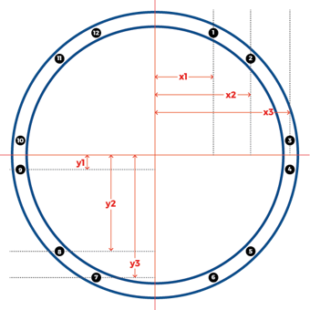
Moments of force are vector qualities with magnitude and direction. Their magnitude is the product of the magnitude of the force and the “moment arm”: the distance between the path of force and the center of rotation.
Overturning moments are calculated using the center of mass and the time-history responses of the force sensors (response channels) in pre-defined configuration. The mass center is the mean location of the payload’s mass.
Key Considerations
- Sensor mounting direction
- Sensor preload and setup
- Virtual channel formula
- Sum of X, Y, Z
- Overturning Moment of X, Y, Z
Virtual channels in VibrationVIEW can calculate overturning moments in real time. Engineers can set force limits to these values to prevent over-testing the payload, particularly at higher level random tests.
Overturning moments of multiple response channels have a moment arm distance multiplier. In VibrationVIEW, the output of a virtual channel where distance is multiplied by the difference between channels will have the appropriate torque unit.
Processed Data Calculations
In addition to linear math operations via virtual channels, engineers may need to perform more complex calculations on processed data. Often, these include calculations that use processed data to account for extreme scenarios.
Typically, processed data calculations are for safety or to cover outlier scenarios that time-domain virtual channels may not effectively capture. VibrationVIEW can perform these more complex functions using the calculation notch functionality in Random test mode.
For example, VibrationVIEW can compute the live vector force at multiple points/axes and apply a force limit to the vector force.
Calculation Notch in Random
In Random, VibrationVIEW performs processed data calculations using the processed PSD data from physical channels. The calculation notches display the result and notch line as defined in the test profile.
Phase is effectively removed from the calculation and will not influence the result as it would in time-domain virtual channels. Engineers can use the data to analyze and limit any extreme or worst-case scenarios and apply safety guardrails.
FLVT requirements typically reference notching functions. In VibrationVIEW, additional parameters can be defined to abort a test, statistics can be monitored or analyzed, and full spectrum aborts can be applied. In combination, these actions define a test that protects the product, achieves the desired test result, and gives the user complete access to the data.
How to Use Virtual Channels for FLVT
You can access virtual channels in the Inputs dialog or by selecting Configuration > Virtual Channels. User-defined virtual channels will appear on the Channel Notch tab of the Sine or Random test. You can apply a notch to the virtual channel just as an input channel.
Virtual Channel Example Configuration
A simple configuration using four triaxial force sensors will be used for the following example. The time-domain summation and overturning moment calculations utilize the X-Y coordinates of each position and the appropriate axis of measurement.
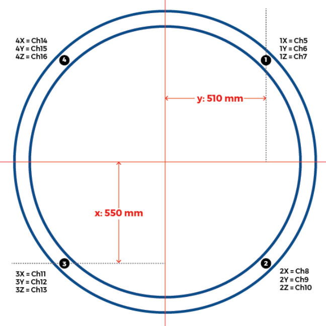
| Position 1 (510,550) | Position 2 (510,-550) | Position 3 (-510,-550) | Position 4 (-510, 550) |
| 1X = Ch5 | 2X = Ch8 | 3X = Ch11 | 4X = Ch14 |
| 1Y = Ch6 | 2Y = Ch9 | 3Y = Ch12 | 4Y = Ch15 |
| 1Z = Ch7 | 2Z = Ch10 | 3Z = Ch13 | 4Z = Ch16 |
Formulas
XSUM = Ch5+Ch8+Ch11+Ch14
YSUM = Ch6+Ch9+Ch12+Ch15
ZSUM = Ch7+Ch10+Ch13+Ch16
m(X) = (550)(Ch7)+(−550)(Ch10)+(−550)(Ch13)+(550)(Ch16)
m(X) = 550(Ch7-Ch10-Ch13+Ch16)
m(Y) = (−510)(Ch7)+(−510)(Ch10)+(510)(Ch13)+(510)(Ch16)
m(Y)=510(-Ch7-Ch10+Ch13+Ch16)
m(Z) = (510*Ch6−550*Ch5) + (510*Ch9−(−550)*Ch8) + ((−510)*Ch12−(−550)*Ch11) + ((−510)*Ch15−(550)*Ch14)
m(Z)= 510(Ch6+Ch9-Ch12-Ch15) + 550(-Ch5+Ch8+Ch11-Ch14)
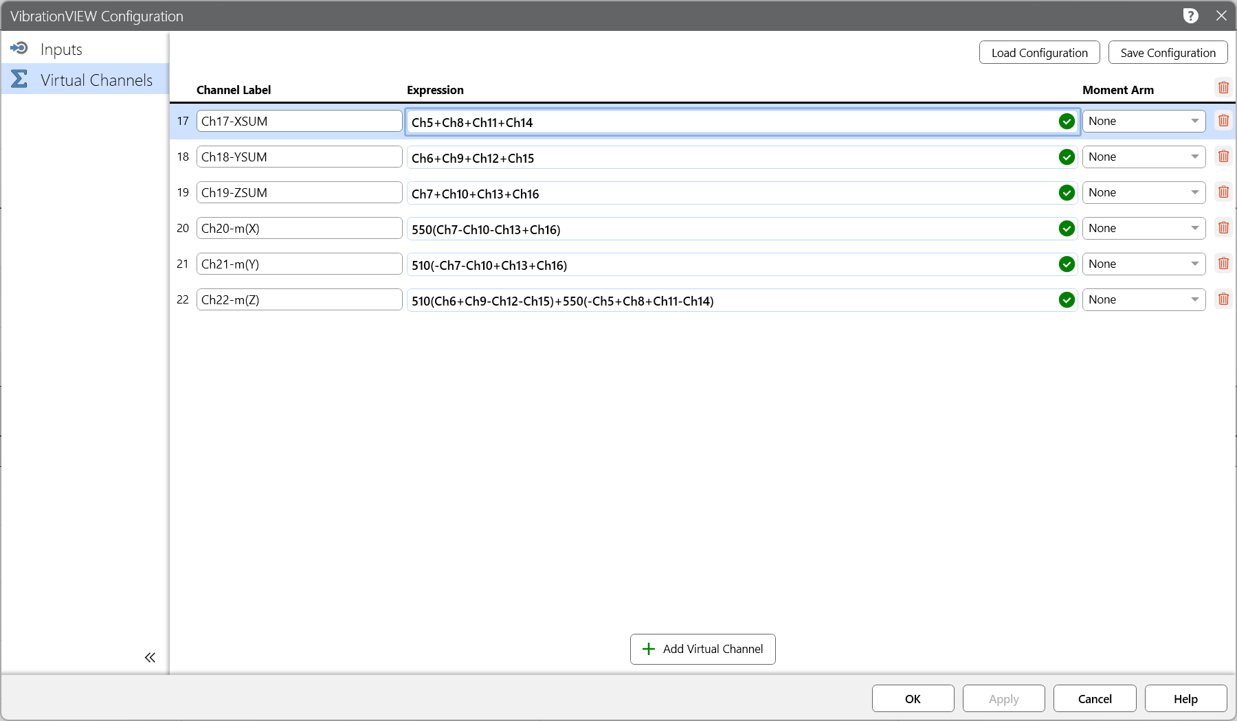
VibrationVIEW will assign a torque unit to the output of the overturning moment calculations.
Determining Force Limits
Over-testing can result in weight and performance penalties, which can be great for highly resonant configurations. However, engineers should not use force limiting to compensate for test specifications, and the force and acceleration values should be within reason. The force limit should follow acceleration specifications and normally derive from previous tests.
Force limits largely derive from the mechanical impedance of the flight mounting structure and the DUT’s response to flight conditions. Engineers may use finite element analysis (FEA) or another analysis type to estimate this structural dynamic response or reference previous flight data.
According to MIL-STD-810H, engineers must use field data to justify force limiting. The control limits should reflect field data measurements and consider the sensitivity of the DUT to resonance.
Why Employ Force Limiting?
Force limiting is a cost-effective method to prevent over-testing associated with hard mounting on the shaker head. Shaker tests tend to be more severe than real-world vibration because only the shaker’s force rating limits the energy.
Vibration force limiting more closely simulates the response of the structure in its field environment. For instance, consider a rocket with a payload mounted to the top. The mounting points from the rocket body to the payload are flexible, and the payload can transfer energy to the rocket. The shaker is heavy and dense and does not deform from the energy imparted onto it. An engineer would use force limiting to limit the total input force at each mounting point to the force experienced in a rocket launch.
Engineers should consider force limiting when the impedance between flight conditions and the test setup is significantly different.
FAQs
What is the purpose of force limiting, and how does it differ from other test limits?
Force limiting functions to reduce over-testing due to the mechanical impedance of the shaker setup. On a wider scale, its purpose is to bring the test configuration closer to the flight boundary conditions. Force limits measure the base input forces, whereas traditional limits measure the acceleration (or velocity, displacement, etc.) response at various points on the shaker system or DUT.
Purpose of Force Limiting
- Replicate real world environmental forces
- Minimize potential damage from overturning moments
- Reduce resonance over-amplification due to rigid mounting
What is shaker mechanical impedance?
A shaker’s mechanical impedance refers to the shaker’s response to force at the DUT’s attachment point. Typically, flight equipment is lightweight with a low mechanical impedance, meaning it responds freely to an input force. It is attached to structures like shelves, bulkheads, panels, and brackets.
Equipment hard-mounted to a shaker system shows a relatively higher mechanical impedance. Engineers must account for a shaker’s mechanical impedance so that the test setup accurately reflects the flight conditions.
Which sensors should I use?
Force limiting controls both the input acceleration and reaction force and, as such, requires force transducers and control accelerometers. Triaxial piezoelectric force gages are recommended. PCB Piezotronics provides a helpful guide to force sensors as well as several considerations for installation in the following technical article.
How else can I avoid over-testing?
Over-testing is often a product of unrealistic test specifications. A shaker system setup in a laboratory can produce much harsher conditions than in-flight conditions. To avoid over-testing, engineers can create test profiles from flight data or compare the fatigue damage potential of a profile to flight data prior to testing.
Where can I find more information?
NASA-HDBK-7004C offers practical considerations for force limiting vibration.