Use the COLA output on a VR controller hardware as a secondary control loop and control the DC offset of a select input channel. The user can specify which channel to use for closed-loop control as well as the scaling factor for the DC output.
DC Offset Control allows the COLA output on the VR9700/VR10500 to function as a secondary control loop. In doing so, the user can control the DC offset of a selected input channel.
The user can specify which channel to use for closed-loop control. The input must be configured as a DC input and have the same unit category as the DC signal.
COLA Output
The COLA output provides a voltage sync signal to external equipment. Aside from DC Offset Control, the COLA output can be differential, sine, or square, or can function as a DC frequency reference, a phase-controlled second output for multi-axis testing, or control only.
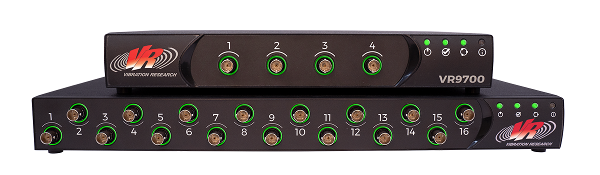
VR Controller Hardware
VR9700 I/O Unit
Vibration Research’s high-powered control hardware for vibration and shock testing. Scalable to 128 channels and compatible with all electrodynamic and servo-hydraulic shakers. Features include up to 256 kHz sample rate and 2 outputs.
VR10500 I/O Unit
Vibration Research’s high channel count control hardware for vibration and shock testing. Scalable to 512 channels and compatible with all electrodynamic and servo-hydraulic shakers. Features include up to 256 kHz sample rate and 4 outputs for multiple shakers.
DC Offset Parameters
The DC Offset parameters control the functionality of DC Offset Control. The user can define the scaling factor for the DC output using the units and Volts parameters. The parameters also control the DC Offset Reference option.
DC Offset Reference
The DC Offset parameters also control the DC Offset Reference option. DC Offset Reference uses the COLA to output an open loop DC voltage proportional to a user-configured engineering unit. The desired output level is configured on a per schedule level basis within the test settings.
DC Offset Control for Armature Centering
DC Offset long stroke shaker
Control Motor Operation
With the optional Motor Control add-on, the user can schedule motor operation in the Sine software. For example, an engineer can control a shaker and drive the test item’s motor simultaneously.
The VibrationVIEW software performs motor control by using the COLA as a DC Offset Reference or DC Offset Control. The controller outputs a DC signal proportional to the user-specified value.
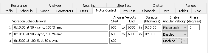
In the Motor Control settings, the user enables, disables, or phase locks the angular velocity and sets the phase value.
Enabling the angular velocity brings the motor to the user-specified level
Phase Lock enables the output and locks the phase between the drive signal and the external motor to the user-specified phase value
The Disable option disables the motor and prevents the COLA from sending a DC signal
The user can also use the motor control settings to configure a sine sweep by defining start and end levels and a sweep rate.