Rapid failure mode precipitation testing (RFMPT™) is a test to failure that engineers can use at any time throughout their product development cycle, from proof of concept to post-production verification and validation. As a test-to-failure, RFMPT demonstrates a product’s robustness to harsh end-use environments and customer use. As an integrated process of a product development plan, it is an efficient and cost-effective way to track reliability growth.
Instead of reading this article, you can view the Tech Talk.
When to Use RFMPT
- Proof of concept
- Prototypes
- A/B comparisons
- Reliability growth tracking
- Test setup shake-down
- Late design changes
- Robustness demonstrations
- Manufacturing process changes
- New downstream supplier
- Large components/systems
- Digital twin boundary condition confirmation
Engineers perform A/B comparison tests to prove out a design fix or confirm that a cost-savings idea does not lead to warranty headaches later. The RFMPT philosophy lends well to A/B comparisons, and it is ideal for quickly and confidently validating manufacturing process changes, new downstream suppliers, and late design changes without long-duration or hardware-intensive testing.
Engineers can also add RFMPT to success-based validation test plans. After their test parts pass success testing, they can apply RFMPT to a subset of test parts to benchmark robustness.
RFMPT is an adaptable, combined environmental test philosophy that can also help work out bugs in more targeted test setups, confirm parameters for digital twins, and ensure that hardware is ready for full validation test flows. Finding and fixing problems before investing in a large production of prototypes is a cost and time savings opportunity.
Product Development Cycle
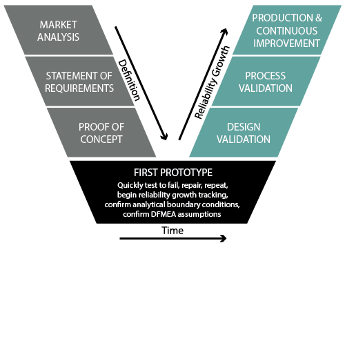
RFMPT can identify design weaknesses at any point in the product development cycle, whether early in the concept phase, to uncover manufacturing defects before full production, or for continuous improvement after the product is in the field.
Definition
For a typical product development cycle, the statement of requirements should identify all product performance, safety, and reliability requirements for the design’s specific customer application.
A comprehensive design failure mode effects analysis (DFMEA) should call out RFMPT in the proof-of-concept phase. It can root out obvious design flaws and confirm the upper and lower environmental operational points and design destruct limits. Engineers should perform this analysis early and with a relatively small number of parts on test and repeat it as they identify failures and evaluate proposed solutions. Engineers can also use this time to test system elements, such as a circuit card or cooling loop seal design.
After a design passes the proof-of-concept phase, the DFMEA should use RFMPT as design control for early prototype testing and preventive control to provide realistic boundary conditions for digital twin analyses.
Reliability Growth
For the reliability growth side of the product development cycle, RFMPT becomes a tool for shaking down test hardware before producing many prototypes for full validation testing. It is also an element of process failure mode effects analysis (PFMEA), ensuring that process changes, late component or supplier substitutions, or minor design changes are directionally correct in terms of minimal time, hardware, and lab resources and robust against failure in the end-use environment. The RFMPT test philosophy also provides post-production confirmation of cost savings initiatives, warranty fixes, or other product/process changes.
Objective
The objective of RFMPT is to establish a design margin for the most common stressors that generate the most failure modes.
Figure 1 is an example of a full RFMPT setup for a power inverter for automotive applications. The test used a simultaneous three-axis hydraulic rig for vibration that fit under a thermal hood. The thermal hood could use focused liquid nitrogen or conventional refrigeration to achieve the desired thermal ramp rates.
In addition to real-world vibration and thermal stressors, the power inverter units were subjected to humidity while undergoing real-world electrical loads that simulated electric motor driving and regenerative braking conditions.
Typical RFMPT Failure Modes
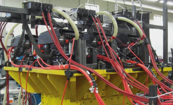
Figure 1. RFMPT setup for a power inverter.
- Loose connections
- Structural cracks
- Coolant leaks
- Sealing breaches
- Broken welds
- Electrical shorts/loss of isolation
- Material degradation
- Thermal runaway (batteries)
- Solder joint failures on circuit cards
- Mechanical wear out
- And more
Process
- Identify test goals
- Match to design phase
- Failure criteria
- Establish baseline environmental/usage
- Define stress levels and correlate to end-use environment
- Employ appropriate operation modes
- Repair and continue to ultimate failure
- Identify operational and foolish failure limits
- Teardown and improve design
- Repeat
- Track reliability growth
As with any test, RFMPT must have the proper scale (component/subsystem/system). Engineers can employ the RFMPT philosophy for any of these testing levels.
The test must replicate real failure mechanisms/modes by using inputs correlated to the end-use environment through damage modeling as defined by performance and safety requirements specified in the application’s technical documents.
Engineers should include the operational parameters related to mechanical or electrical cycling in the test setup where possible. These characteristics should be articulated in a comprehensive DFMEA with clear expectations for critical inputs and at what levels and cycle counts. Other necessary details include which failure mechanisms drive which failure modes, how failure modes are represented in the test setup, and which performance criteria are used to establish failure.
The engineer should also accelerate the test to minimize test time but avoid foolish failures due to over-acceleration.
In the end, RFMPT is a test-to-failure that requires on-the-fly repairs, which allows the test to continue in a controlled step-stress fashion to failure. It is compatible with A/B comparisons and reliability growth tracking. Engineers should compare RFMPT results to a knowledge base for math models to confirm the validity of analyses done in parallel. Expect the unexpected and update your DFMEA with any new information that will speed up the next product development cycle.
Test Environments
RFMPT employs as many environmental variables as a product requires and as a test lab can simulate. The test inputs should correlate to the end-use environment using any of the several damage models readily available for this purpose.
- Thermal cycling: Coffin-Manson
- Thermal aging: Arrhenius
- Humidity: Peck
- Vibration: fatigue damage spectrum (FDS)
- Mechanical shock: shock response spectrum (SRS)
- Mechanical cycling
- Electrical cycling
- And others
The benefit of using field data and damage models to correlate a test to the customer environment cannot be overstated. First, field-correlated models build confidence that the identified test failures are probable in the field. They allow engineers to fix the right things for the right reasons and are necessary for defining virtual twins or math model boundary conditions. Finally, they establish the appropriate test acceleration factors.
We want to be sure that our testing only produces true failures for the right reasons.
RFMPT Test Sequence
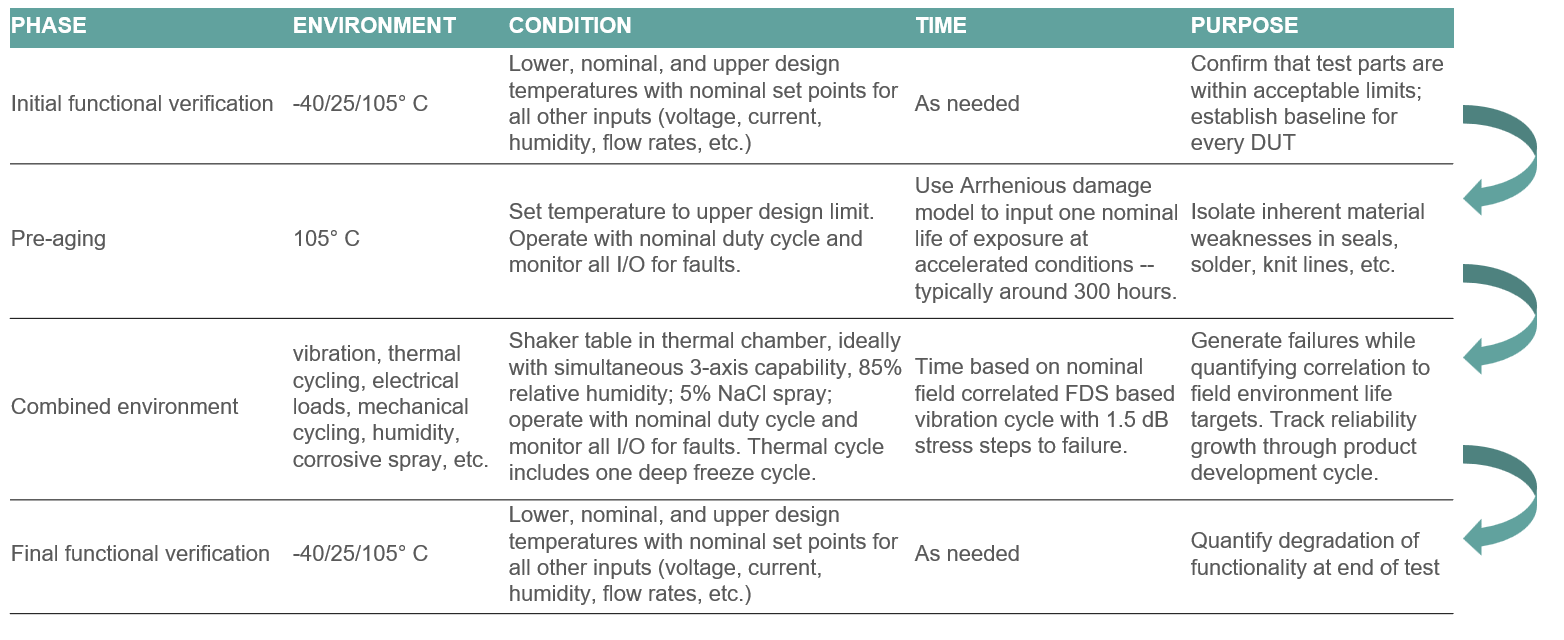
RFMPT progresses in essentially four phases. The first phase establishes that the parts on test are suitable. It measures critical performance characteristics at nominal design environmental corner points to do so.
The second phase is “pre-aging.” Generally, it exposes test parts to an elevated temperature for some period to isolate inherent material weaknesses in seals, solder, injection mold knit lines, etc. Pre-aging can also involve mechanical shock, mechanical or electrical cycling, electronics burn-in, etc.
The heart of the RFMPT test is the combined environmental testing, particularly vibration and thermal cycling. The testing performs vibration inputs in an increasing step-stress fashion in which each increasing step correlates to one product lifetime (if using the Vibration Research Fatigue Damage Spectrum methodology). We will talk more about this method later.
Finally, the test performs an end-of-test full functional verification identical to the initial functional verification to identify latent defects, quantify degradation, and produce data for A/B comparisons and reliability growth tracking.
Temperature Profile
The RFMPT thermal cycle exposes the test parts to one peak hot and peak cold cycle per vibration step-stress cycle. It also uses thermal cycles with smaller temperature changes for the duration of the vibration test to accumulate as much thermal damage as possible.
Understanding how the number of thermal cycles corresponds to accumulated end-use environment thermal exposure helps to explain field reliability and track reliability growth. Thermal characterization of test article ramp rates versus the thermal chamber verifies 1) that the chamber is optimized for all test part locations and 2) that true thermal cycling can be related to the correlated damage model, particularly if the product has solder joints under test. Understanding the relationship between test parts and the test chamber is also necessary to optimize the cycle for test efficiency.
Vibration Profile
Appropriate vibration profiles are necessary for successful RFMPT. For many products, this means having separate profiles by axis. Ideally, engineers should run an RFMPT test on an electrodynamic, servo-hydraulic, or servo-electric multi-axial vibration system. However, engineers can make various adaptations using a single-axis shaker by enveloping the profiles (least desirable) or testing each axis separately.
In Figure 2, the product was tested over a 10 to 2,000Hz bandwidth with different amplitudes by axis, which appropriately excite various resonances based on Vibration Research FDS analyses. As we will discuss next, the RFMPT process increases vibration amplitudes by 1.5 dB increments.
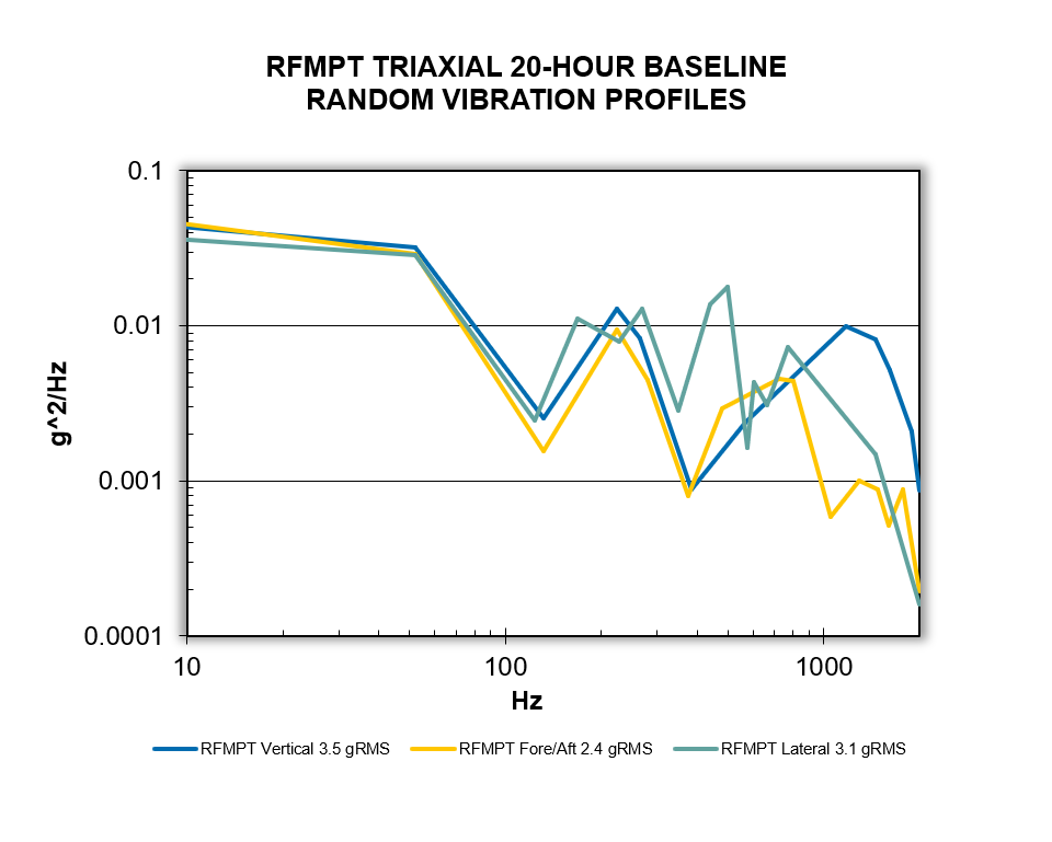
Figure 2. Triaxial vibration profiles with different amplitudes by axis.
Establishing Vibration Levels
The first or baseline vibration level in an RFMPT test subjects the test article(s) to one equivalent product life. Engineers can determine the product life by processing measured data with the FDS software and accelerating the test time such that the amplitudes do not exceed the SRS limits.
Running the first vibration tests at this level establishes the likelihood that the part will pass its performance, reliability, and safety requirements at end of life. However, RFMPT is a test-to-failure. Accordingly, if the parts survive the baseline level, the test level increases by 1.5 dB and runs again for a shorter period, exposing the test parts to a second-lifetime equivalent of vibration fatigue damage. Figure 3 is the vertical profile from the SAE J2380 vibration standard for electric vehicle batteries.
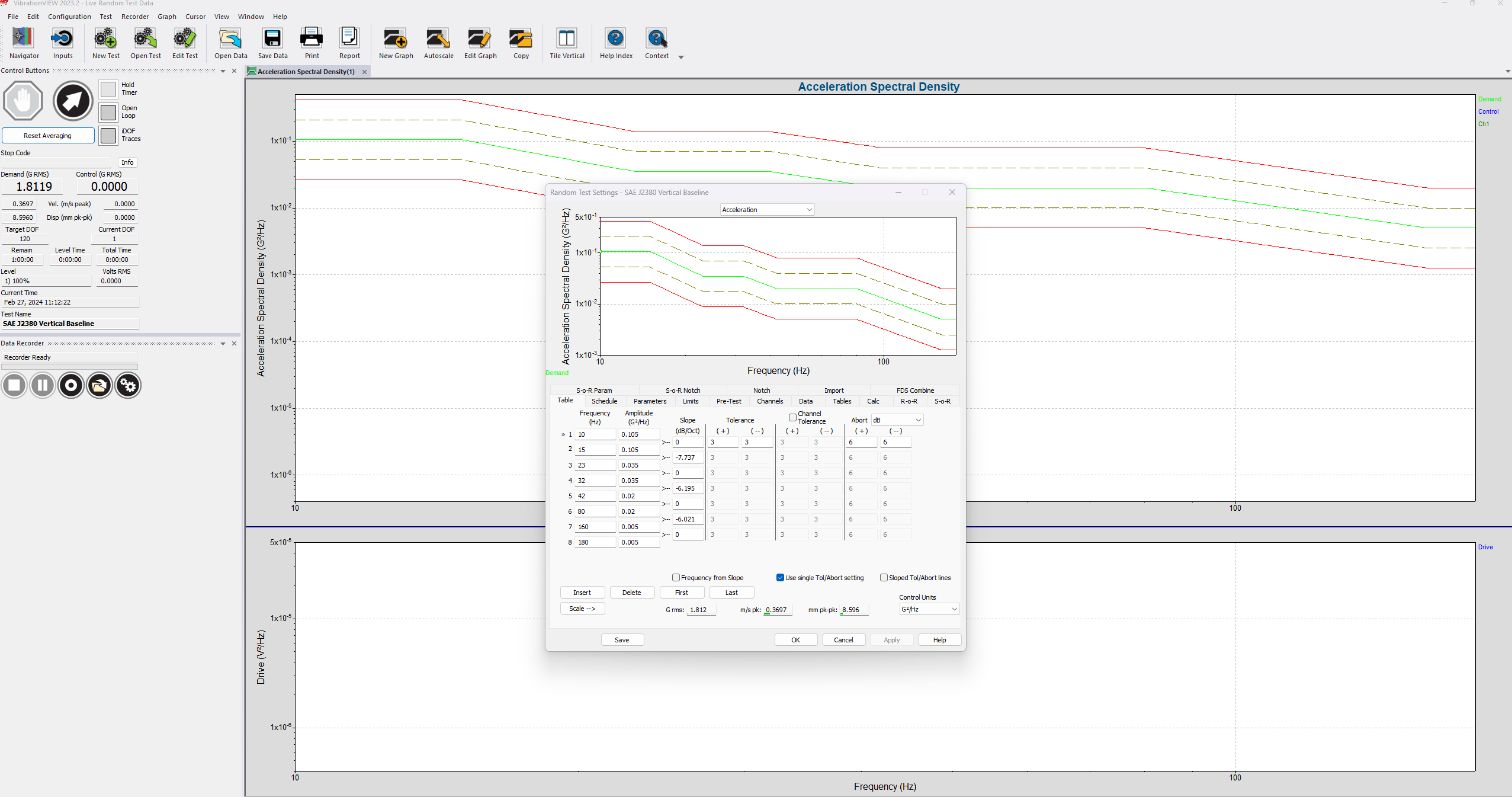
Figure 3. SAE J2380 vibration profile in VibrationVIEW.
Increasing the amplitude by 1.5 dB and shortening the test time to maintain the equivalent of one product life fatigue continues until the test achieves enough unrepairable failures to apply statistics for reliability growth tracking. In this example, the process continued for six vibration levels to 7.5dB.
Vibration Level Summary
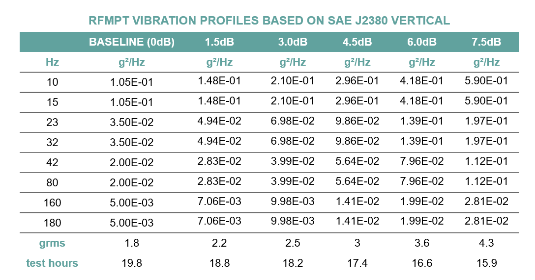
This example used the SAE J2380 vertical vibration profile as a baseline. It based the time acceleration on a well-known formula for accelerating a vibration profile from gRMS levels:
(1) 
The initial RFMPT level ran for 19.8 hours at 1.8gRMS. At the sixth level, the test ran for 15.9 hours at 4.3gRMS.
The vertical baseline test for SAE J2380 is 5.5 hours. However, RFMPT correlates to a desired reliability target, so it uses a sampling plan that relates the number of parts on test to how many “product lives” a part must survive to demonstrate a reliability requirement.
This example used six parts on test with a 0.9995 reliability at 50% confidence. The baseline test was 5.5 times 3.6 or 19.8 hours. Vibration Research’s Tech Talk describes this concept in more detail.
FDS Software
Engineers can create a correlated baseline vibration profile with the VibrationVIEW FDS software. They can combine multiple waveforms representing different events, such as highway driving, rough road driving, high torque, etc. The product’s target life defined in its design specifications is the starting point for accelerating the vibration test to get the baseline profile representing one product life. Finally, Vibration Research’s patented Kurtosion can help engineers more closely replicate the peak distribution found in the end-use environment.