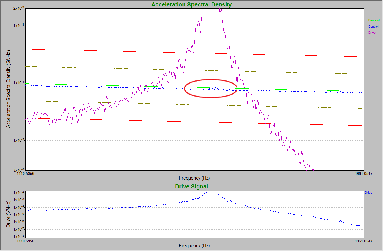
Finally, they ran a test on the shaker head alone to view the effect of notching on a control channel.
Test 1
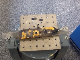
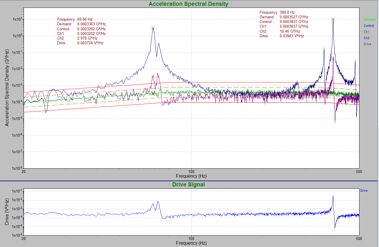
The engineer ran the test with no notching on Channel 2, which they mounted at the end of the lawnmower blade. The control was on the shaker head. Figure 2 displays the NAVMAT test on a lawnmower blade with no notching. Notice the large resonances on the mower blade (Ch2) in the 70 to 80Hz range and the 300 to 400Hz range.
Test 2
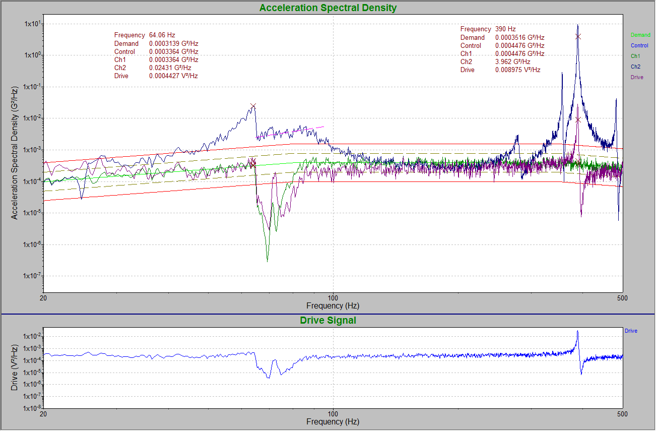
Next, the engineer re-ran the test with a notch at the 65 to 95Hz range for Channel 2. They set the amplitude level at 65Hz to 0.0025g2/Hz and 95Hz to 0.0055g2/Hz. In doing so, the notch limited the large resonances (2.98g2/Hz) in Test 1 (Figure 3).
Test 3
The engineer ran the test without notching but set the control to Channel 2. The drive compensated to keep the lawnmower blade’s large resonances to a minimum, i.e. within the tolerance and abort lines (Figure 4). To do so, the drive signal dipped at the 65 to 95Hz range, similar to when it was notched (Figure 3). It also dipped in the 300 to 500Hz range.
The lawnmower blade’s large resonances were reduced across the PSD spectrum (Ch2) because of the low-level drive signals at those resonances.
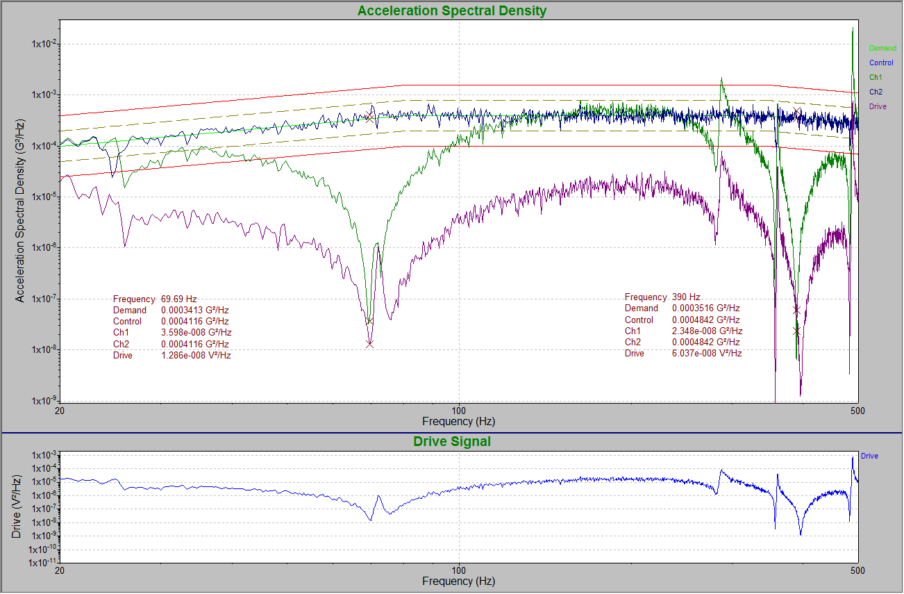
Figure 4. NAVMAT test on a lawnmower blade with control on the end of the lawnmower blade (Ch2) with no notching.
Test 4
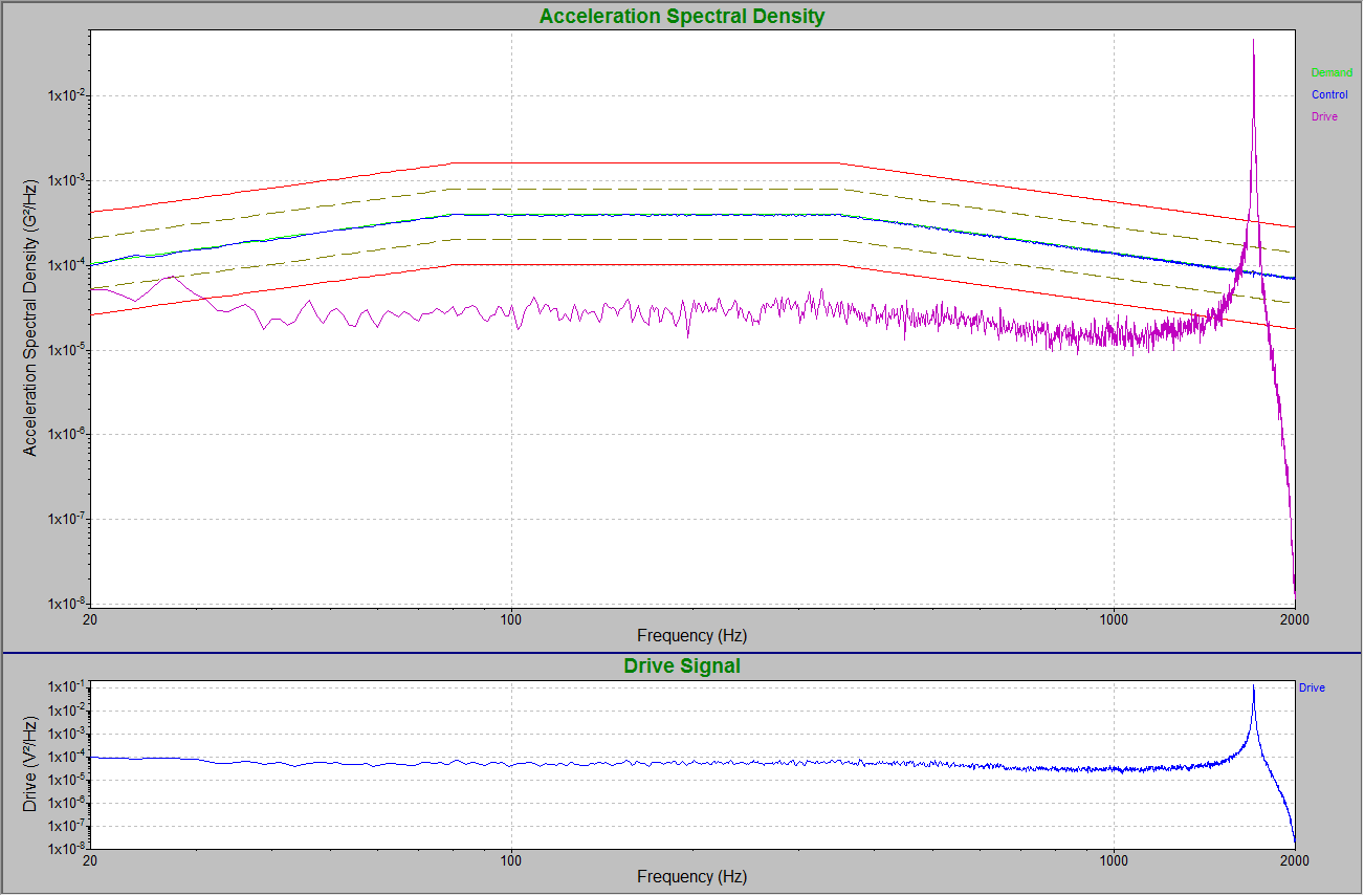
In the final test, the engineer ran the NAVMAT profile on the shaker head alone. They determined that the shaker head had a resonance at approximately 1,700Hz (Figure 5). They then added a notch (boost) at the shaker head’s resonance (1,690 to 1,715Hz). See Figures 6 and 7. The drive signal without the boost (Figure 5) produces the same outcome as the boost (Figure 6).
Benefits of Notching
When discussing random control notching, it is appropriate to separate the discussion into two subtopics: the benefits of notching for response channels and notching for control channels.
Response Channels
For a response channel, the test engineer can set boundaries for large resonances that may appear in the test of a specific product. With notching, the test engineer can avoid certain resonances while still testing others. In Figure 3, the low-frequency resonance (70 to 80Hz) was eliminated, but the higher frequency (300 to 400Hz) was tested.
Some advocate that notching is unnecessary because the drive compensates for the resonances in a product. Controlling on the end of the lawnmower blade rather than the shaker head seems to reduce the drive input and control the resonances on the lawnmower blade, but it does so across the entire frequency spectrum (Figure 4). This outcome is not desirable. Reducing the resonances in this manner affects the entire frequency band rather than the narrow frequency band of the one or two resonances of interest.
Control Channels
As displayed in Test 4, there is no need to use notching for control response resonances. The drive compensated for the notch across the 1,700Hz resonance of the shaker head (Figure 7) in the same way when no notch was in place (Figure 6).
Conclusion
Notching is helpful when dealing with unwanted resonances on response channels. Test engineers should use a notch on a response channel to avoid a particular resonance when testing other resonances. Although the drive compensates for resonances in a product, it does so across the frequency spectrum. Therefore, it is wise to use notching in appropriate locations to avoid testing around unwanted resonances and still be able to test others.
However, as far as control channels are concerned, there is no need to use notching because the drive signal accomplishes the same goal as the notch on the control channel.

