For industries where it is necessary, low-frequency random testing is vital to safety and reliability. Low-frequency energy (0.1 to 10Hz) can be the culprit for engineering faults in transportation, packaging, and seismology. The consequences can range from passenger discomfort to catastrophic damage to a structure. However, low-frequency random vibration testing has several limitations engineers must consider.
Low Frequency and System Limits
 First, engineers performing low-frequency testing can run into issues with high displacement. With less frequent vibration oscillation, there is more time for the shaker to apply force in one direction, and errors from the measurement system can amplify the displacement. Low-frequency energy can approach the shaker’s displacement limits and risk damage to the armature, such as in a case of an over-stroke.
Product and sensor configuration may also have displacement limitations. For example, a displacement sensor may have a range of ½ inch maximum displacement before incurring damage.
Displacement clipping can prevent a high and potentially damaging displacement value. However, the current clipping methods for removing peaks also have limitations.
Clipping Displacement at Low Frequencies
A test engineer aims to generate a random vibration profile that meets the required response without over-testing at certain frequencies. They want to make sure there is enough energy to test at the low frequencies without tripping the system limits.
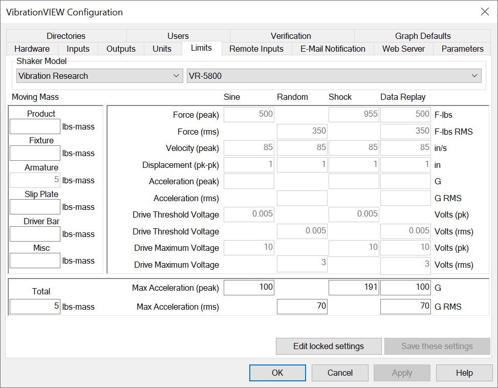
For random vibration testing, electrodynamic shaker acceleration is rated by the root-mean-square (RMS) and force. A random test’s demand power spectral density (PSD) specifies a frequency shape and RMS level but does not include a peak level.
Engineers are interested in peak displacement rather than RMS because shaker displacement limits are rated as a peak-to-peak value. Gaussian random vibration does not have an absolute peak value, but an average peak value is obtainable. The average peak level at one side of the equilibrium is about three times the RMS value. For peak-to-peak displacement, this average is doubled.
Clipping—a method of signal manipulation—has been claimed to solve issues with high-displacement drive signals. Ideally, clipping should limit peaks above or below a defined level. However, standard clipping methods do not perform as intended or result in issues more severe than the original. As engineers still require the results clipping is said to deliver, Vibration Research developed an improved clipping method to limit displacement: TruClip™.
Clipping Based on the Control Measurement
Engineers can use TruClip to constrain movement within the limits of the shaker. With TruClip, they can convert the signal to displacement before clipping, ensuring an accurate clip for the measurement type.

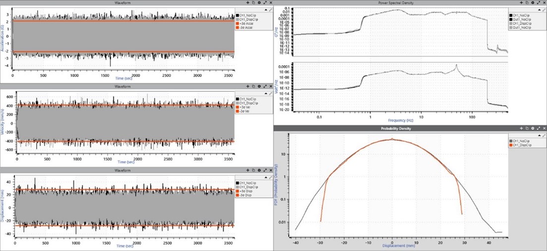
TruClip applied to displacement data.
Other clipping methods clip the drive output, which does not lead to a clipped control input. Most likely, generic clipping methods will not limit shaker stroke or force nor protect the device under test (DUT).
Clipping displacement peaks with TruClip will drop the shaker’s peak level without affecting the RMS, given that the clip is not extreme (below 3-sigma). Therefore, the engineer can use moderate clipping to avoid a peak value while maintaining the target RMS level.
Clipping the Amplifier Output
A low-frequency/high-displacement signal also poses the risk of exceeding the amplifier drive voltage. The amplifier delivers energy to the shaker that equates to the drive signal. The test will abort if a high-displacement drive signal requires more voltage than the amplifier can generate.
TruClip is the best option for clipping the product input to limit shaker stroke. However, TruClip does not clip the amplifier voltage because it replicates clipping at the control input, not the drive output. Therefore, if engineers want to limit displacement to avoid exceeding amplifier limits, other clipping methods, such as silent or digital clipping, are a good option. However, engineers should note that although these clipping methods will clip at the drive output, the high-displacement peaks will still appear on the shaker table.
How to Access TruClip
TruClip is a feature exclusive to the VibrationVIEW Random software. Current customers can try a demo of the feature by reaching out to their sales representative. New customers can request a quote or download a demo of the software.

