Abstract
This tech note delves into using a response channel to develop a new demand test profile for random vibration testing. This function proves helpful in many applications. The following uses a combination of an accelerometer and microphone for control and monitoring.
Question
A customer asked if there is the ability to control a vibration test with something other than an accelerometer. Further, they’d like to know how to generate a new test profile (demand) based on the response of a monitor signal that may or may not be an accelerometer.
The original question relates to performing circuit board HALT/HASS-type testing in an acoustically driven vibration test chamber. This test method achieves the required vibration levels on the circuit board by controlling sound.
Answer
The following method uses an accelerometer on channel 1 as the initial control and a microphone on channel 2 as the response. The idea is to “capture” the spectrum of the response channel, make a new test profile, and then control the test using the microphone.
This application is applicable to circuit board testing, where an acoustic test system performs HALT/HASS-type testing. The first sample is tested with a lightweight accelerometer or laser vibrometer to achieve the desired vibration on the circuit board. Then, the sound profile is generated based on the microphone response. After the sound profile required to produce the desired vibration is determined, the test technician can quickly remove and replace test samples without needing to mount an accelerometer. This test method is ideal for a high volume or production test environment.
Step 1
To get started, the input configuration must be defined for the accelerometer and microphone. To define sensor configuration, select Configuration > Inputs. Enter the sensitivity and units for the sensors. The accelerometer should be on Ch1 and the microphone on Ch2.

Inputs configuration in VibrationVIEW. The accelerometer should be on Ch1 and the microphone on Ch2.
Step 2
Enter the desired random vibration profile (New Test > Random). On the Test Settings Channels tab, set the control channel to channel 1.
Step 3
Make sure the accelerometer is mounted and the microphone properly placed, and then start the test with acceleration control. The test should run for a short period to achieve control within the tolerances of the acceleration profile.
Step 4
While the test is running with acceleration control on channel 1, display channel 2 in the current Acceleration vs. Frequency graph. Alternatively, create a new graph defined as Acceleration vs. Frequency and turn off all selections for control, abort, tolerance, etc. aside from channel 2. This will create a new graph that displays the sound pressure profile.

Step 5
While the test is running under acceleration control, create a new random test profile by selecting Test > Generate Random Profile > from Ch2. The shortcut Ctrl+2 is available for customers with the Random Import software (not standard with the Random software).
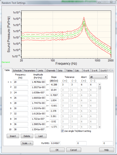
The software will generate a breakpoint file using the current channel 2 data. The figure below shows the new test settings with the automatically generated breakpoint profile in the microphone units Pa^2/Hz.

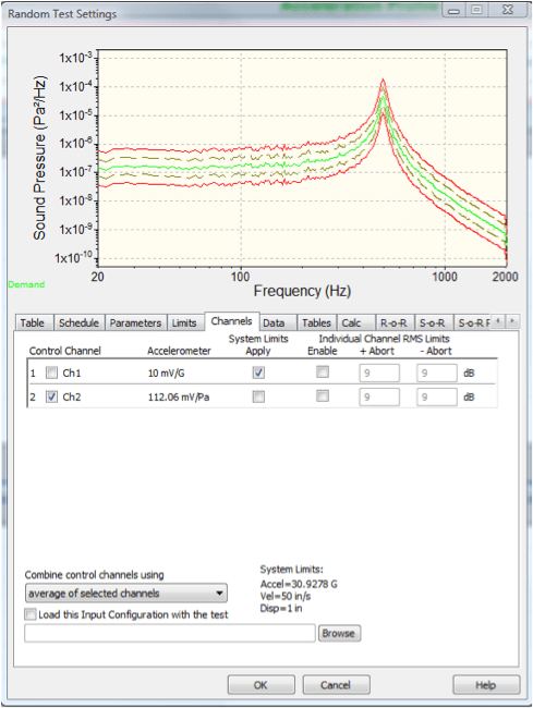
VibrationVIEW will also automatically select channel 2 as the control channel.

Step 6
The saved test profile can now run the vibration test with acoustic control on channel 2.
Other Uses
This method of test profile generation is also helpful when an accelerometer cannot be placed on a certain area of the test item during testing, possibly due to applied heat or a component being electrically hot. Ch1 can initially be at the point of the desired vibration level and Ch2 can be an accelerometer or other sensor in a safe area that can be used as control later.
